Accurate current measurement in high-power industrial circuits remains notoriously difficult due to thermal instability and resistance variance. Here is the hard truth: Even a 0.5% deviation in feedback data can lead to catastrophic battery management failures or expensive motor drive downtime. Precision DC 션트 offer the stability and low-resistance path required for exact monitoring, bridging the gap between high-power flow and control logic. This guide covers selection, installation, and optimization for professional engineers.
1. What Is a DC Shunt and Why Is It Critical?
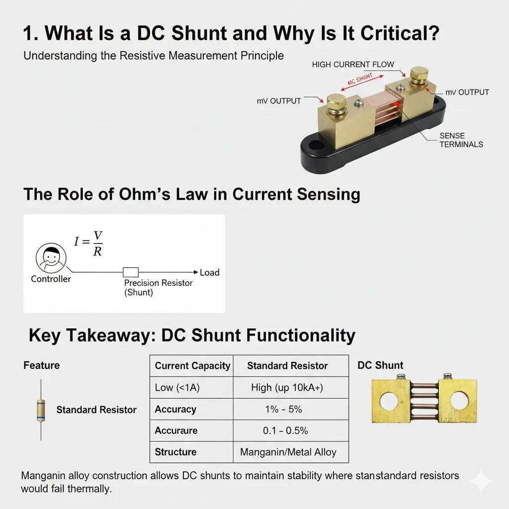
Understanding the Resistive Measurement Principle
A DC shunt acts as a precision resistor placed in series with a load to generate a voltage drop proportional to the current. You might be wondering: why not use a standard resistor? Standard components cannot handle high amperage without burning out or drifting significantly. Having basic knowledge about DC current shunts helps engineers understand why specialized alloys are necessary for stability.
The Role of Ohm’s Law in Current Sensing
Fundamental operation relies on Ohm’s Law (
), where known resistance allows a controller to calculate current based on millivolt drop. Here’s the deal: precise calibration of that resistance value stands as the only barrier between accurate data and system error. Engineers rely on this fixed value remaining constant regardless of environmental stress.
Key Takeaway: DC Shunt Functionality
This component bridges gaps between high-power flow and low-voltage control logic.
| Feature | Standard Resistor | DC Shunt | |
|---|---|---|---|
| Current Capacity | Low (<1A) | High (up to 10kA+) | |
| Accuracy | 1% – 5% | 0.1% – 0.5% | |
| Structure | Carbon/Film | Manganin/Metal Alloy |
Manganin alloy construction allows DC shunts to maintain stability where standard resistors would fail thermally.
2. How Do You Select the Optimal DC Shunt Rating?

Calculating Continuous vs. Peak Current
You must select a DC shunt rated higher than your maximum continuous current to prevent overheating and ensure long-term reliability. But here’s the kicker: industry best practice suggests derating a shunt to operate at only 66% of maximum capacity for continuous use. Operating constantly at 100% capacity invites thermal runaway and permanent drift.
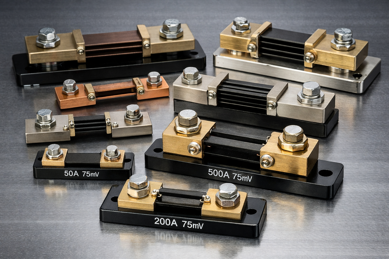
Choosing the Correct Voltage Output
Standard outputs are typically 50mV, 75mV, or 100mV at full rated current. A higher voltage drop provides better resolution for sensing circuits but generates more waste heat. Engineers must balance signal clarity against thermal constraints. Lower voltage drops reduce heat but require more sensitive amplification.
Key Takeaway: Selection Parameters
Proper sizing balances signal strength against thermal dissipation.
| Parameter | Recommendation | |
|---|---|---|
| Derating Factor | 0.66 (Continuous Load) | |
| Standard Output | 75mV (General Use) | |
| Resistance | 0.01Ω to 0.0001Ω |
Over-sizing amperage rating improves longevity but may reduce signal-to-noise ratio if voltage drop becomes too small.
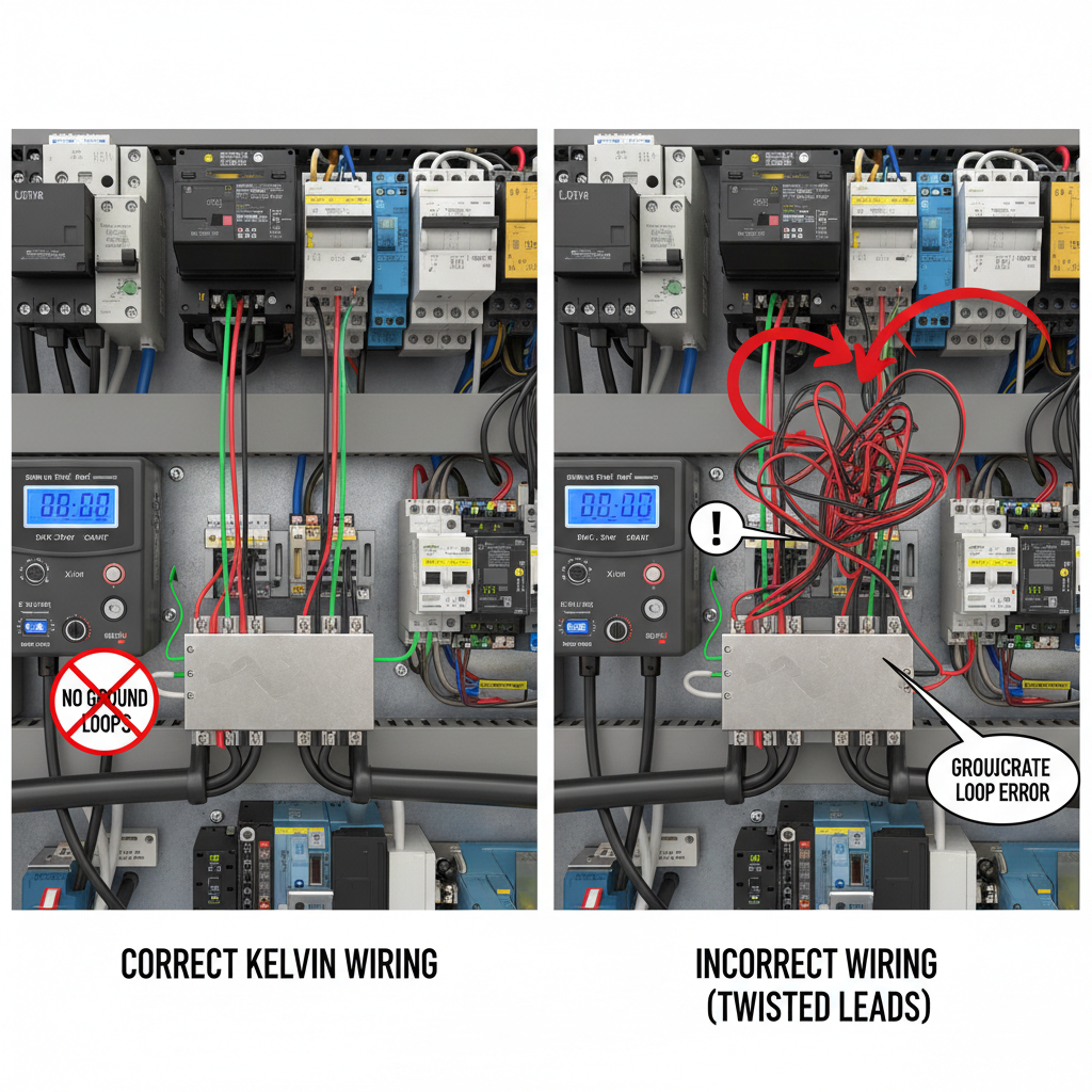
3. Why Is Kelvin Connection Vital for a DC Shunt?
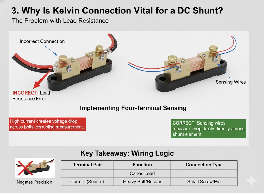
The Problem with Lead Resistance
In high-current applications, the resistance of the connecting wires can often exceed the calibrated resistance of the DC shunt itself. This is where it gets interesting: measuring across current-carrying bolts introduces massive errors due to voltage drop in connections. Even milliohms of wire resistance distort readings significantly when high amperage flows.
Implementing Four-Terminal Sensing
Kelvin connections utilize two separate pairs of terminals: one pair for high current and one pair for voltage measurement. This eliminates lead resistance from measurement equations entirely. Voltage sensing leads carry negligible current, meaning no voltage drop occurs along them.
Key Takeaway: Wiring Logic
Four-terminal sensing is non-negotiable for precision measurement.
| Terminal Pair | 기능 | Connection Type | |
|---|---|---|---|
| Current (Source) | Carries Load | Heavy Bolt/Busbar | |
| Sense (Voltage) | Measures Drop | Small Screw/Pin |
Connecting sensing wires to large bolts instead of dedicated sense screws negates precision.
4. How Do You Physically Install a DC Shunt?

Mounting for Thermal Dissipation
Ideally, you should position the DC shunt on a panel or heatsink with blades vertical to maximize airflow and absorb excess thermal energy. Ideally, orientation promotes natural convection cooling. Horizontal mounting traps heat between resistive blades, accelerating degradation.
Torque Specifications and Busbar Connections
Loose connections create hotspots that can melt resistive elements or alter calibration. Always use a torque wrench to secure busbar connections to manufacturer specified values. High resistance at contact points generates heat that migrates into sensing elements, causing drift.
Key Takeaway: Mechanical Stability
Physical installation directly impacts electrical performance.
| Step | Action | |
|---|---|---|
| Orientation | Blades Vertical | |
| Fastening | Calibrated Torque | |
| Clearance | >10mm from other parts |
Incorrect mounting orientation can reduce current handling capacity by up to 20% due to poor convection.
5. What Factors Degrade DC Shunt Accuracy?

Understanding Tolerance Classes
High-quality DC 션트 come in strict tolerance classes, typically 0.25%, 0.5%, or 1.0%, which defines their static error offset. What’s the real story? A 0.5% tolerance means a 100A reading could actually range between 99.5A or 100.5A. This deviation matters significantly in precise applications like Coulomb counting for battery packs.
The Impact of Aging and Oxidation
Over time, repeated thermal cycling causes resistive alloys to age, slightly changing resistance values. Our precision current sense resistors utilize advanced alloys to minimize drift caused by repeated thermal cycling and oxidation over time. Environmental factors like humidity corrode terminals if plating fails.
Key Takeaway: Stability Metrics
Accuracy is dynamic and degrades without proper selection.
| Factor | Impact on Accuracy | |
|---|---|---|
| Initial Tolerance | Static Error Offset | |
| Aging | Slow Drift over Years | |
| Temperature | Dynamic Fluctuation |
Selecting tighter tolerance reduces initial error but does not prevent drift from aging or heat.
6. How Does Thermal Drift Affect DC Shunt Data?
Temperature Coefficient of Resistance (TCR)
TCR measures how much resistance changes as components heat up, usually expressed in ppm/°C. Manganin is utilized because its ultra-low TCR ensures the DC shunt resistance remains stable even as the component reaches its operating temperature limits. You need to know this: High TCR materials introduce massive linearity errors as load increases.
Thermal EMF Explained
When different metals join at different temperatures, they generate small voltages (Seebeck effect) that distort readings. This parasitic voltage adds to measured drops, creating false current data. Symmetrical thermal design helps cancel out these effects across terminals.
Key Takeaway: Thermal Management
Heat is the primary enemy of precision in resistive sensing.
| Material | TCR Value | Application Suitability | |
|---|---|---|---|
| Copper | ~3900 ppm/°C | Poor (Drifts wildly) | |
| Manganin | ~15-20 ppm/°C | Excellent (Stable) |
Using copper traces instead of specialized DC shunts introduces massive thermal errors software calibration cannot easily fix.
7. Where Are DC Shunt Resistors Commonly Deployed?
Battery Management Systems (BMS)
In electric vehicles and storage arrays, the DC shunt tracks State of Charge (SoC) by precisely integrating current flow over time. Here is the reality: without precise shunts, BMS cannot accurately predict remaining battery range. Small errors accumulate over hours, leading to large SoC discrepancies.
Industrial Motor Drives and Welding
Robust DC current measurement solutions are required to withstand harsh inductive spikes and vibration common in heavy machinery environments. Shunts endure physical abuse better than fragile electronic sensors. Welding equipment relies on them for consistent arc control.
Key Takeaway: Versatile Applications
From renewable energy to heavy industry, shunts are ubiquitous.
| Industry | 기능 | Criticality | |
|---|---|---|---|
| EV / Auto | SoC Monitoring | High | |
| Solar | Inverter Input | Medium | |
| Welding | Current Control | High |
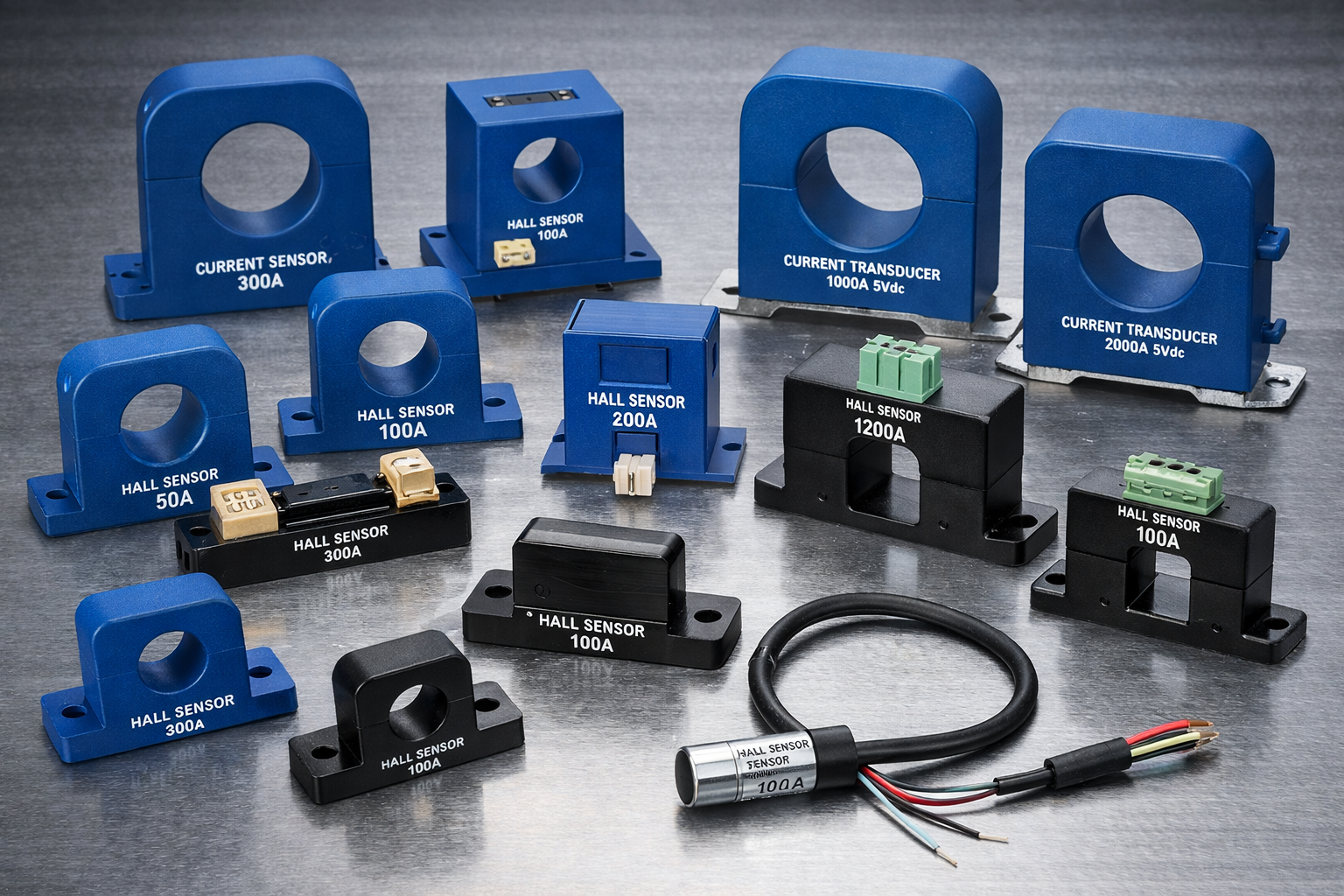
Rugged metal alloy shunts prove superior to Hall effect sensors in high-vibration, high-magnetic-field welding environments.
8. How Do You Interface a DC Shunt with Digital Meters?
Signal Conditioning Requirements
The raw millivolt output from a DC shunt is often too small and noisy for direct microcontroller input without amplification. You typically need operational amplifiers or dedicated current-sense amplifiers to scale signals. Ready for the good part? Modern amplifiers feature zero-drift architecture to match shunt precision.
High-Side vs. Low-Side Sensing
This is a crucial decision: Low-side sensing (ground path) is simpler but creates ground loops. High-side sensing (supply path) acts safer for systems but requires specialized differential amplifiers handling high common-mode voltage. Industrial designs favor high-side topology for fault detection capabilities.
Key Takeaway: Integration Logic
Interface circuits determine quality of digital data.
| Method | Pros | Cons | |
|---|---|---|---|
| Low-Side | Simple, Cheap | Ground Noise | |
| High-Side | Detects Shorts | Complex Circuit |
High-side sensing is preferred in modern industrial designs to ensure systems detect short circuits to ground.
9. How Do You Troubleshoot DC Shunt Errors?
Identifying Zero-Offset Drift
If your meter reads current when the load is disconnected, you likely have a thermal EMF issue or a DC shunt ground loop affecting the signal. Ready for the fix? Verify temperature across terminals is uniform and check for ground potential differences. Uneven cooling often causes this phantom voltage.
Checking for Physical Damage
Overheating often manifests as discoloration on resistive blades or melted insulation on sense wires. Visual inspection acts as the first line of defense against failing components. Look closely: oxidation on connection points suggests poor torque or harsh environments.
Key Takeaway: Maintenance Steps
Routine checks prevent catastrophic measurement failure.
| Symptom | Probable Cause | Fix | |
|---|---|---|---|
| Drifting Value | Overheating | Improves Cooling | |
| Erratic Data | Loose Bolt | Torque Check | |
| Non-Zero Null | Thermal EMF | Equalize Temps |
Most “shunt failures” actually stem from installation failures involving loose connections or inadequate ventilation.
10. What Safety Protocols Apply to DC Shunt Usage?
Isolation and High Voltage Hazards
Although voltage drop is small, the DC shunt itself may be floating at hundreds of volts relative to ground, presenting a significant shock hazard. Never forget: touching a shunt during operation can prove fatal in high-voltage DC systems. Isolation barriers are mandatory for operator safety.
Fire Prevention and Fusing
A short circuit downstream draws massive current through shunts, potentially turning them into heating elements. Always install fast-acting fuses in series with shunts to protect physical structures. Safety first: Unfused measurement lines risk melting insulation and starting fires.
Key Takeaway: Risk Mitigation
Treat shunts as live, high-energy conductors.
| Hazard | Prevention | |
|---|---|---|
| Shock | Polycarbonate Cover | |
| Fire | Series Fuse | |
| Burns | Cage / Barrier |
Installing clear plastic covers over shunt blocks remains a standard safety requirement in UL-certified control panels.
Conclusion
Selecting the right DC shunt involves balancing resistance, power rating, and thermal management. Correct installation using Kelvin connections ensures the precision required for modern B2B applications supported by LEEYD . Always prioritize thermal stability and safety isolation in your design.
Ready to upgrade your system’s accuracy? Contact us today to discuss custom DC shunt solutions tailored to your specific voltage and current requirements.
FAQ 섹션
Q1: Can I use a DC shunt to measure AC current? Answer: Yes, but with limitations. While standard DC shunts can measure low-frequency AC, inductance becomes a significant error factor at higher frequencies, distorting voltage waveforms.
Q2: Why is my DC shunt getting extremely hot? Answer: This usually indicates the shunt is under-rated for the current load. Power dissipation follows
; if current is too high or airflow is blocked, resistive energy converts to dangerous heat.
Q3: What is the best voltage drop rating for a shunt? Answer: 75mV is the industry standard for most measuring instruments. However, 50mV is preferred for high-efficiency systems to reduce power loss, while 100mV offers higher signal resolution in noisy environments.
Q4: Should I install the shunt on the positive or negative side? Answer: Installing on the negative side (Low-Side) is easier for metering but can cause ground loops. Installing on the positive side (High-Side) is safer and detects ground faults but requires an isolated amplifier.
Q5: How often does a DC shunt need calibration? Answer: For critical industrial or laboratory applications, annual calibration is recommended. In standard power monitoring, a visual inspection and connection torque check every 12 months is typically sufficient.