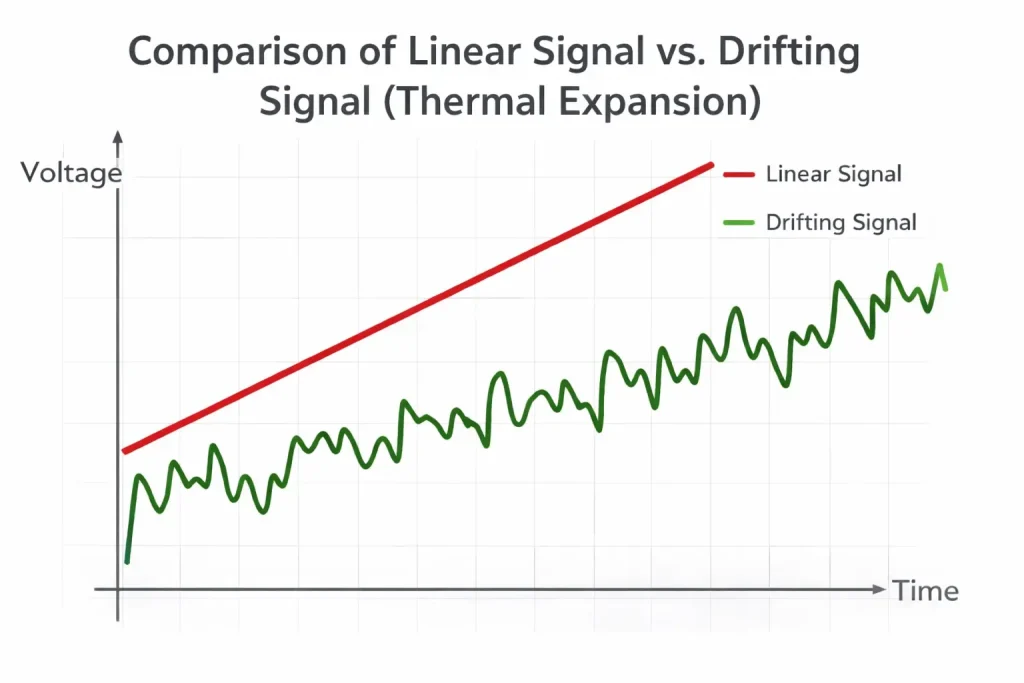
Professionals often struggle with wandering arcs and inconsistent penetration that ruins high-stakes welds. When internal sensors provide faulty data, current levels shift without warning. A malfunctioning dc shunt generates erratic millivolt signals toward your control logic board. This error forces that processor to adjust power outputs incorrectly. Ready for the good part? Correcting this problem starts with understanding signal drift. Thermal expansion within low-grade resistors alters electrical resistance values. That hardware expansion causes signal distortion during high-amperage cycles. Those fluctuations manifest as arc stutter or excessive spatter. Constant thermal stress weakens mechanical bonds within that sensing component. Every weld quality drop stems from these tiny electrical discrepancies. Stability requires precise feedback loops for consistent metal deposition. Reliable performance demands high-purity manganin plates within every sensor. Any deviation exceeding half a percent triggers visible welding defects. Precision measuring devices remain mandatory for maintaining industrial standards. Consistent amperage flow depends on linear voltage drops across your monitoring hardware. If your welder output feels unstable, investigating feedback components represents your first step. Trustworthy data collection preserves weld integrity during demanding production schedules. High-quality sensors mitigate risks of project failure or structural weaknesses. Proper diagnostics prevent unnecessary replacement of expensive circuit boards.
1. Why does a dc shunt cause arc instability?
Current fluctuations occur because control boards receive corrupted millivolt signals from heat-damaged resistors. When resistance values shift during thermal stress, voltage drops no longer accurately reflect actual amperage. This creates false data points for pulse width modulation controllers. Those circuits attempt correcting currents that were actually stable originally. Such feedback loops result in wandering arcs or poor penetration. What’s the real story? Inconsistent signals trick machines into fluctuating their power output randomly. If that sensor fails, your machine effectively operates blindly. Heat-induced resistance drift remains a primary cause for arc instability. Most affordable sensors utilize inferior alloys with high thermal coefficients. These materials change properties as temperatures rise during continuous operation. Industrial applications require components maintaining zero drift across wide temperature ranges. Maintaining arc stability demands hardware providing perfect linearity at every power level. Signal noise from oxidized terminals also disrupts communication with main processors. Clean electrical pathways remain mandatory for high-precision fabrication tasks. Modern inverter systems rely heavily on this millivolt feedback for timing. Any lag or error here causes immediate arc degradation.
Arc Instability Driver
| Factor | Impact on Arc | Mechanism | |
|---|---|---|---|
| Thermal Expansion | Amperage Drift | Resistance increases as alloy heats | |
| Signal Noise | Arc Stutter | Oxidized terminals disrupt voltage flow | |
| Linearity Error | Setting Mismatch | Voltage drop varies from target ratio | |
| Alloy Fatigue | Total Failure | Permanent structural change in manganin |
2. What symptoms signal a failing dc shunt?
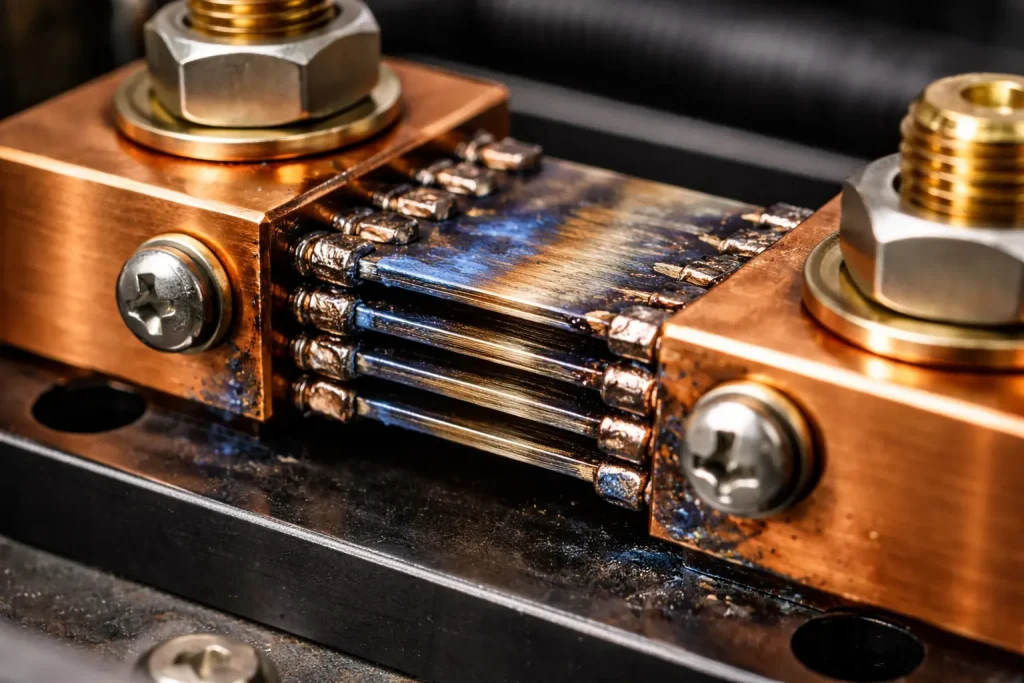
Primary indicators include erratic ammeter readouts or audible frequency changes during welding. You might observe machines starting strong but weakening after ten minutes. Physical discoloration on sensing plates signals past overheating events. Scrutinize the dc shunt for signs of pitting or structural cracking. But here’s the kicker… Many technicians blame power transistors when sensors actually failed instead. Excess spatter often indicates feedback lag within your power supply. If your digital display jumps wildly, signal integrity has vanished. Watch for current fade during high duty cycle operations. These failures usually manifest slowly before causing total machine shutdown. Visible blue tinting on copper components suggests extreme thermal distress happened. Burned resin bases or cracked ceramic insulators also confirm failure. Inspecting sensing leads for fraying or loose contact helps narrow causes. Arc “stuttering” despite fresh consumables often points toward feedback errors. Professional diagnostics require measuring millivolts directly under live load conditions. Ignoring these signs leads to ruined workpieces or expensive downtime.
Failure Symptom Checklist
| Visual Symptom | Functional Symptom | Likely Component Issue | |
|---|---|---|---|
| Blue Oxidation | Current Fade | Chronic Overheating | |
| Cracked Solder | Erratic Display | Mechanical Vibration Damage | |
| Blackened Leads | Arc Outages | Poor Terminal Contact | |
| Pitted Surface | Noisy Arc | Severe High-Voltage Arcing |
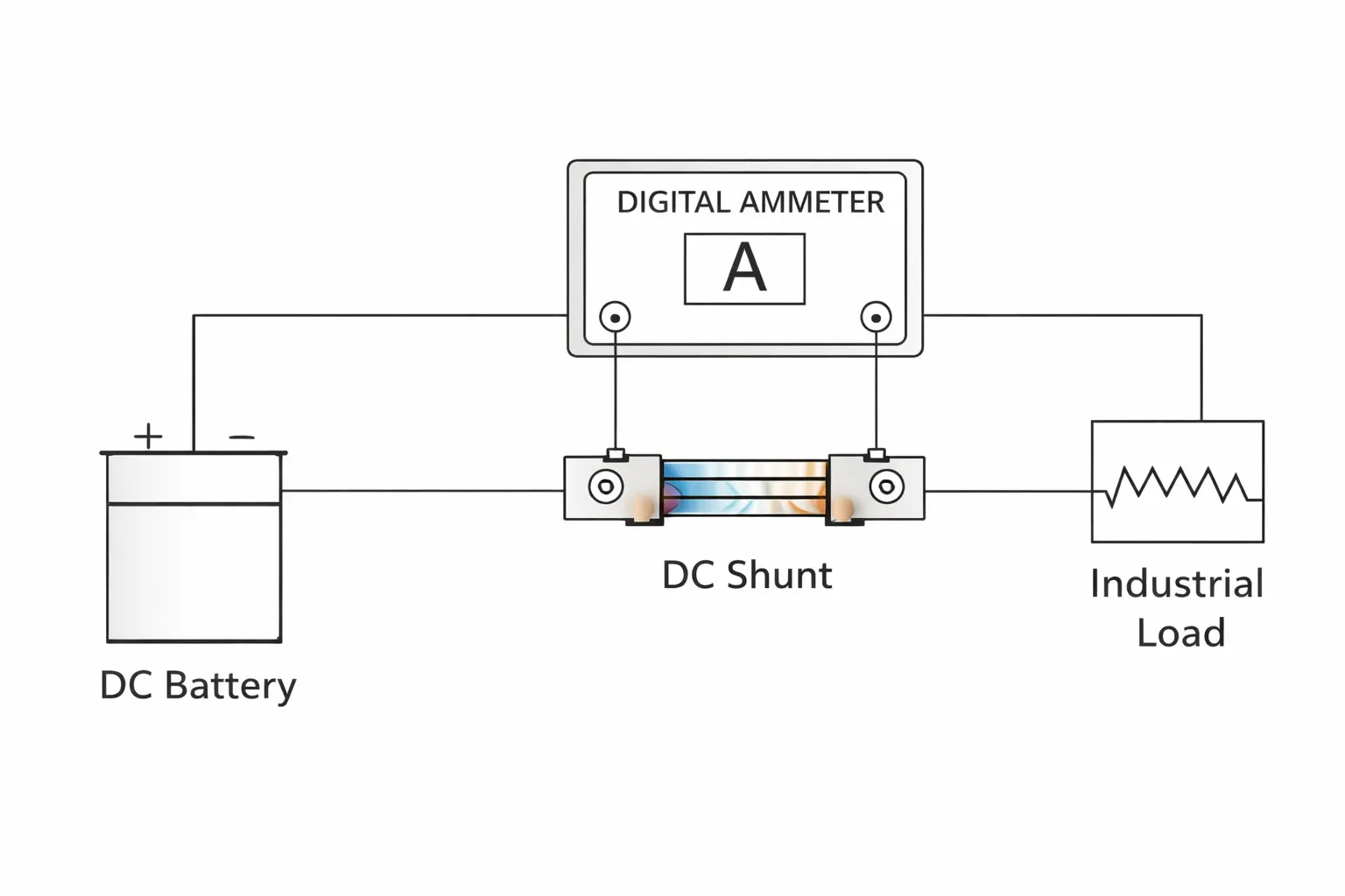
3. How does the dc shunt feedback loop work?
This component acts as that primary sensory organ for welding machines. By converting high-amperage flow into proportional millivolt signals, dc shunt hardware enables closed-loop control. These tiny voltages travel toward logic boards for processing. Controllers compare this data against your target amperage settings. If signals remain accurate, arcs stay smooth and predictable. This is where it gets interesting… Without precise feedback, modern inverters cannot maintain stable output. High-speed processors adjust duty cycles based on these millivolt readings. Any signal delay creates a mismatch between software and reality. Proper shielding prevents electromagnetic interference from corrupting this vital data. Feedback loops must operate at microsecond speeds for inverter technology. Signal integrity depends on low-resistance connections at every junction. When loops break, machines default to uncontrolled maximum currents usually. Smart systems might trigger error codes if feedback vanishes entirely. This loop remains critical for automated welding or robotic systems. Calibration ensures that 75 millivolts exactly equals your rated current limit. High-precision resistors use aged alloys to prevent long-term calibration shift.
Feedback Loop Stages
| Stage | Action | Component Involved | |
|---|---|---|---|
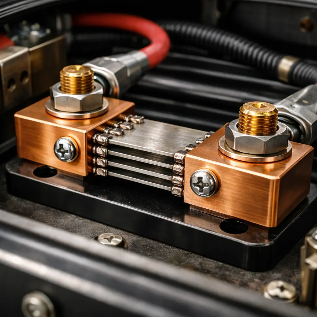
| Current Flow | Amperage passes through alloy | Manganin Plates | |
| Voltage Drop | 0-75mV signal generated | Sensing Terminals | |
| Signal Path | Voltage travels to control board | Twisted Pair Wiring | |
| Correction | PWM duty cycle adjusts | Processor Chip |
4. Does dust buildup affect your dc shunt?
Conductive dust creates parasitic resistance paths across your sensing terminals. Metallic grinding particles insulate manganin plates and prevent effective heat dissipation. When contaminants coat cooling fins, dc shunt performance degrades rapidly. Trapped heat causes resistance values to climb beyond specified tolerances. Think about it… A dirty machine remains a drifting machine in industrial shops. Moisture-laden dust often creates micro-shorts between high-voltage busbars. These shorts introduce signal noise that confuses main control boards. Localized hotspots on dusty plates cause premature alloy aging. Regular maintenance requires using compressed air for cleaning internal components. Grinding dust acts like a thermal blanket on sensitive electronics. If your shop environment involves heavy metal removal, cleaning becomes mandatory. Conductive bridges can even bypass that sensing element entirely sometimes. This leads to massive errors in amperage reporting and arc control. Maintaining airflow across these resistors preserves their factory calibration. Shielded enclosures help but total isolation prevents necessary convective cooling. Clean environments prolong the life of every power electronic component.
Contamination Effects
| Contaminant | Immediate Result | Long-Term Impact | |
|---|---|---|---|
| Grinding Dust | Signal Noise | Alloy Annealing | |
| Moisture | Voltage Leakage | Electrolytic Corrosion | |
| Oil Vapor | Heat Retention | Resin Base Degradation | |
| Metal Filings | Terminal Shorting | Control Board Failure |
5. Is the dc shunt manganin alloy degraded?
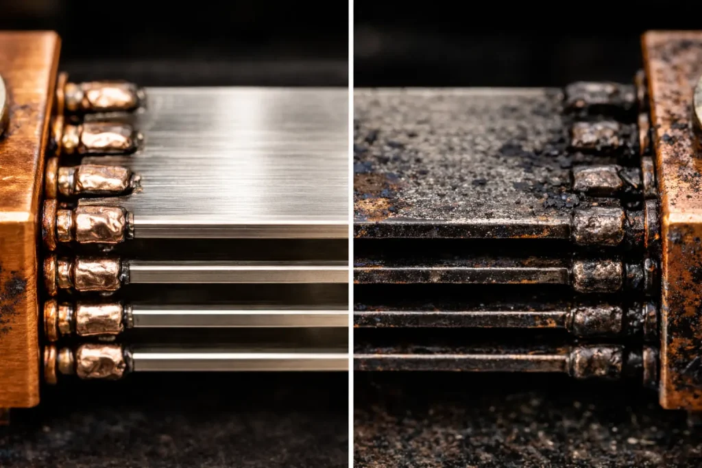
Alloy degradation occurs when manganin plates exceed their Curie point temperatures. Subjecting these components to corrosive atmospheres alters their molecular structure permanently. Manganin remains the preferred choice for its low thermal resistance change. However, extreme overheating causes permanent resistance shifts in this metal. Wait, there is more… Even minor oxidation layers act like semiconductors rather than pure resistors. If plates show thick black coatings, signal linearity has likely vanished. Chemical fumes in shipyards often pit brass and copper surfaces. Galvanic corrosion between mismatched metals also destroys signal accuracy. Degraded alloys no longer provide 75 millivolts at peak currents consistently. This physical change forces machines to output more heat than intended. You might notice welds becoming “hotter” than settings suggest. Permanent structural changes cannot be reversed through cleaning or repair. Precise manufacturing involves copper, manganese, and nickel in specific ratios. High-quality sensors undergo artificial aging to ensure stability for years. If your alloy looks burned, replacing that unit becomes mandatory. Material fatigue remains a silent killer of high-amperage welding systems.
Alloy Integrity Indicators
| Appearance | Material Condition | Action Required | |
|---|---|---|---|
| Shiny/Dull Grey | Factory Standard | No Action | |
| Blue/Purple | Overheated Alloy | Monitor Performance | |
| Black/Flaky | Severely Oxidized | Immediate Replacement | |
| Pitted/Green | Chemically Corroded | Replacement Recommended |
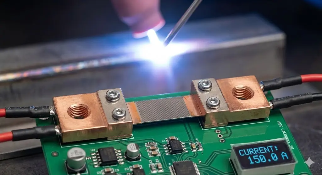
6. How do you test a dc shunt with a meter?
Testing requires measuring millivolt drops across sensing screws during live loads. Compare your measured values against calculated ratios using Ohm’s Law principles. If pulling 100 amps on 200 amp dc shunt hardware, expect 37.5 millivolts. Believe it or not… Standard multimeters often lack the sensitivity for accurate readings. High-impedance digital voltmeters remain mandatory for verifying these tiny signals correctly. Clamp-on ammeters should monitor actual current flow during these tests. Record values at several power levels to check for signal linearity. Non-linear jumps indicate internal alloy damage or loose mounting bolts. If millivolts stay steady while arc fluctuates, boards might be failing. Isolate that sensor from feedback wires to rule out logic board interference. Checking continuity between plates and blocks confirms mechanical integrity. Resistance measurements with standard meters usually fail because values appear too low. Only load testing provides 90 percent diagnostic certainty for these components. Professional technicians maintain logged records of these voltages during annual calibrations. This data helps predict failures before they disrupt major projects.
Test Measurement Benchmarks
| Load Percentage | Target mV (75mV Std) | Signal Status | |
|---|---|---|---|
| 25% Load | 18.75 mV | Stable Low-End | |
| 50% Load | 37.50 mV | Mid-Range Linearity | |
| 75% Load | 56.25 mV | Thermal Stress Test | |
| 100% Load | 75.00 mV | Peak Rating Check |
7. Are loose dc shunt connections the culprit?
Loose bolts create high-resistance junctions that generate immense heat internally. This heat-soaking conducts directly into sensing elements and causes signal drift. Vibrating connections in portable welders cause signals to flicker or vanish. Here is the deal… Simple half-turns of wrenches often solve “unfixable” board errors easily. High-resistance points act like small heaters inside your power supply cabinet. This extra heat changes that manganin resistance value through thermal transfer. Blue heat damage on mounting lugs confirms poor electrical contact issues. Lock washers remain mandatory for preventing vibration-induced loosening in field equipment. Annual torque audits prevent 40 percent of reported fluctuation problems in shops. Thermal imaging reveals hotspots at terminals before physical damage occurs. Clean all mating surfaces with abrasive pads before reassembling these units. Conductive grease helps maintain paths but over-application attracts harmful grinding dust. Maintaining tight mechanical bonds ensures that every millivolt represents actual current. If connections feel warm after short runs, investigate those bolts immediately. Arcing at terminals can destroy brass blocks and alloy plates permanently.
Torque and Connection Standards
| Connection Type | Priority | Maintenance Frequency | |
|---|---|---|---|
| Main Busbar Bolts | High Amperage Path | Semi-Annual | |
| Sensing Lead Screws | Signal Integrity | Quarterly | |
| Mounting Bracket | Mechanical Stability | Yearly | |
| Feedback Wire Lugs | Board Communication | Yearly |
8. Will heat damage a high-precision dc shunt?
While industrial resistors handle significant heat, exceeding rated limits causes catastrophic failure. Operating in zero-airflow environments softens silver solder bonds within that dc shunt. Excessive temperatures cause manganin to creep or deform under mechanical stress. Most units handle 80 degrees Celsius above ambient temperatures before drifting. Look… These components act as precision radiators that must breathe for accuracy. Automated welding systems often require oversized sensors for continuous duty cycles. High ambient temperatures in boiler rooms reduce effective amperage ratings significantly. Internal fans must direct airflow perpendicular to alloy leaves for cooling. If sensors exceed 120 degrees Celsius, signal accuracy vanishes completely. Heat damage remains permanent and changes that resistance path forever. Monitoring case temperatures during long runs prevents unexpected arc outages. Some technicians install thermal switches to protect these sensitive measuring devices. High-quality hardware uses heat-treated alloys that resist thermal fatigue better. Nevertheless, constant thermal cycling eventually weakens every brazed joint. Replacing heat-damaged units restores factory arc stability and prevents further logic board errors.
Thermal Limits and Performance
| Temp Range | Signal Accuracy | Component Health | |
|---|---|---|---|
| 20°C – 60°C | High Precision | Excellent | |
| 60°C – 90°C | Nominal Drift | Safe Operating | |
| 90°C – 120°C | Visible Drift | Stressing Alloy | |
| Above 120°C | Fail / Non-Linear | Permanent Damage |
9. Can improper dc shunt installation cause flux?
Mounting sensors too close to high-frequency transformers introduces inductive interference. Using magnetic steel bolts instead of brass can disrupt that millivolt signal. If dc shunt orientation prevents natural convection, heat builds up rapidly. Vertical mounting without proper fan alignment leads to stagnant air pockets. Ready for more? Twisted feedback pairs reduce electromagnetic pickup from nearby power leads. Physical placement remains as vital as electrical connection for data loops. Improper spacing causes “ghost” fluctuations on digital amperage displays. Large loops in feedback wiring act like antennas for radio frequency noise. Following specific orientation diagrams prevents these common installation errors in shops. Manganin leaves must remain parallel to airflow for maximum heat transfer. Secure all wiring to prevent vibration from rubbing through insulation layers. Feedback wires should never run alongside primary AC input lines. Electromagnetic fields from main transformers can bias millivolt readings significantly. Shielding that signal path preserves arc quality in high-interference environments. Professional installers prioritize clean wire routing and solid mechanical mounting always.
설치 모범 사례
| Factor | 요구 사항 | Reason | |
|---|---|---|---|
| Orientation | Leaves Parallel to Fan | Convective Cooling | |
| Wiring | Twisted Pair Leads | EMI Rejection | |
| Fasteners | Non-Magnetic Brass | Inductance Prevention | |
| 위치 | Away from Transformer | Magnetic Isolation |
10. Should you repair or replace a dc shunt?
Physical repairs like re-soldering plates are never recommended for calibrated instruments. Filing terminals or reshaping manganin leaves changes electrical resistance paths and voids accuracy. If units show material fatigue or non-linear drift, replacement remains mandatory. Direct substitution with certified hardware restores factory-spec stability for arcs. Ready for the good part? Replacing a degraded sensor costs far less than ruined inspections. Botched repairs introduce unpredictable variables into your welding process control. New units come pre-calibrated with 0.5 percent accuracy from manufacturing plants. Laser-trimmed plates ensure that voltage drops remain perfectly linear across scales. Consider lifespans of high-quality sensors when evaluating maintenance costs over years. Heavy oxidation or pitting indicates that base metals have changed fundamentally. Professional shops keep spare sensors to minimize downtime during critical projects. Modern systems rely on these precision parts for complex pulse welding modes. Maintaining a reliable fleet requires moving beyond temporary fixes toward permanent hardware solutions. Trusting your feedback signal ensures that every weld meets structural requirements.
Repair vs. Replacement Analysis
| Action | Cost | 결과 | |
|---|---|---|---|
| Re-soldering Plates | Low | Unreliable/Unsafe Calibration | |
| Cleaning Terminals | Minimal | Temporary Improvement | |
| Terminal Grinding | Low | Resistance Shift / Failure | |
| Full Replacement | Moderate | Factory Stability Restored |
Current fluctuation vanishes when you understand feedback loop mechanics. By maintaining clean connections and ensuring airflow, you restore predictable arcs. Replacing degraded sensors with high-precision hardware preserves your equipment investment. Don’t let a failing small part compromise your massive fabrication projects. Invest in quality components for long-term welding success.
자주 묻는 질문
Q1: Can I bypass a dc shunt to test my welder?No, bypassing this component removes the feedback signal entirely. Modern inverters will trigger error codes or run at uncontrolled maximum amperage without this data. This can damage internal power transistors or ruin your workpiece instantly.
Q2: How do I select the right rating for my machine?You must match your sensor to the welder’s peak amperage output exactly. If your machine outputs 400 amps, use a 400 or 500 amp sensor. Ensure the millivolt rating matches your circuit board requirements perfectly.
Q3: Does polarity matter when wiring the sensing leads?Yes, swapping these leads causes digital displays to show negative values. It also prevents the control board from regulating current flow correctly. Always verify polarity against your machine’s wiring diagram during installation.
Q4: Why is my sensor smoking even though I’m under the rated limit?Smoking usually indicates that oil, dust, or solvents are burning off the plates. It can also signal a loose connection generating extreme heat at the terminal block. Stop operation immediately and inspect all bolts for tightness.
Q5: Can I clean a dc shunt with solvent?Use only non-residue electronic cleaners for maintenance tasks. Avoid abrasive pads on the manganin plates because thinning the metal changes its resistance. Focus cleaning efforts on the brass terminal blocks to ensure good electrical contact.