Introduction
Problem: Industrial welding operations demand absolute precision because a single amperage fluctuation frequently turns perfect joints into expensive scrap metal. Your equipment must deliver consistent current levels, yet standard measurement components often drift significantly when facing intense heat cycles common in fabrication environments. Agitate: Consider the financial impact of recalling hundreds of automotive frames or pipeline sections simply because your feedback loop drifted by two percent during production. Here is the deal: inaccurate current monitoring causes unstable arcs, poor penetration, and dangerous field failures that destroy your engineering reputation while draining your budget. Solution: You can lock in precision by selecting a dc current shunt specifically engineered for your exact amperage range and thermal conditions. LEEYD bridges the gap between theoretical specifications and real-world demands. Trust Statement: With over 30 years of engineering stability, we guide you through technical nuances for selecting perfect shunts for your welding architecture.
1. Why is a precision dc current shunt vital for welding quality?
Maintaining constant current during load fluctuations remains the primary function of any feedback system within modern welding power supplies. When an arc length changes due to hand movement or surface irregularity, voltage shifts occur instantly, requiring your power source to adjust amperage output immediately. You might be wondering why standard sensors fail in these dynamic scenarios. Generic sensors often lack the necessary response time or thermal stability to provide accurate data during these rapid transitions. A high-quality dc current shunt acts as an unblinking eye, detecting micro-second surges that would otherwise cause burn-through on thin gauge sheet metal. Without this real-time feedback, your control system operates blindly, leading to inconsistent weld beads and structurally compromised joints that fail non-destructive testing.
Heat input control correlates directly with amperage accuracy, determining the size and properties of the heat-affected zone (HAZ) in your base material. If your measurement component drifts as it heats up, your welder might output higher current than displayed, effectively overheating the workpiece without warning. This excess heat alters grain structure, promotes cracking, and weakens the final assembly. Key Takeaway: accurate current feedback protects metallurgical integrity. High-precision shunts ensure that the energy delivered matches your qualified welding procedure specification (WPS) exactly. For a deeper look at our precision components, visit our DC Shunt Product Page . Consistent monitoring also protects expensive power supplies from undetected overloads that fry internal electronics. Your shunt serves as the heartbeat of this entire control loop.
Impact of Shunt Precision on Weld Defects
| Defect Type | Cause Related to Current | Shunt Role | |
|---|---|---|---|
| Burn-through | Amperage spike | Detects surge immediately | |
| Lack of Fusion | Low current drift | Ensures maintained output | |
| Porosity | Unstable arc | Stabilizes feedback loop |
2. What current ranges dictate your welding dc current shunt choice?
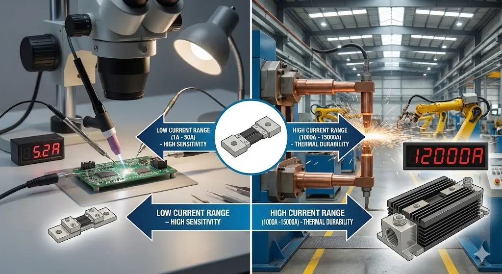
Handling micro-scale applications like TIG welding for electronics or medical devices requires measuring currents often ranging between 1A and 50A with extreme fidelity. In these low-amperage environments, sensitivity matters far more than massive thermal mass because even small deviations ruin delicate components. Here is the kicker: using a high-range shunt for low-current work destroys resolution. A 1000A shunt measuring 5A produces a voltage signal so weak that noise swamps it completely. Therefore, specialized low-current shunts utilize different resistive alloy geometries to generate readable signals at minimal loads. You must select a component rated near your operating maximum rather than oversizing significantly, ensuring your control system receives clear, actionable data for these precision tasks.
Heavy industrial demands for processes like Submerged Arc or Resistance Spot welding push requirements to the opposite extreme, handling loads from 1000A up to 15,000A. These applications generate immense heat and magnetic forces that would physically destroy lighter components. Your selection strategy here prioritizes thermal dissipation and mechanical rigidity over micro-amp sensitivity. Mid-range workhorses for MIG or Stick welding typically fall into the 100A to 500A zone, balancing cost against durability. But wait, there’s more: selecting the wrong range creates immediate safety hazards. For a comprehensive breakdown of range selection, consult our Welding DC Shunt Selection Guide . Matching the physical size and rating of your dc current shunt to the specific process load prevents catastrophic overheating failures.
Welding Processes vs. Current Shunt Needs
| Process | Typical Range | Key Shunt Requirement | |
|---|---|---|---|
| Micro-TIG | 1A – 50A | High Sensitivity (Class 0.2) | |
| MIG/MAG | 100A – 500A | Thermal Durability | |
| Spot Welding | 1kA – 15kA | High Overload Capacity |
3. How does voltage drop impact your dc current shunt selection?
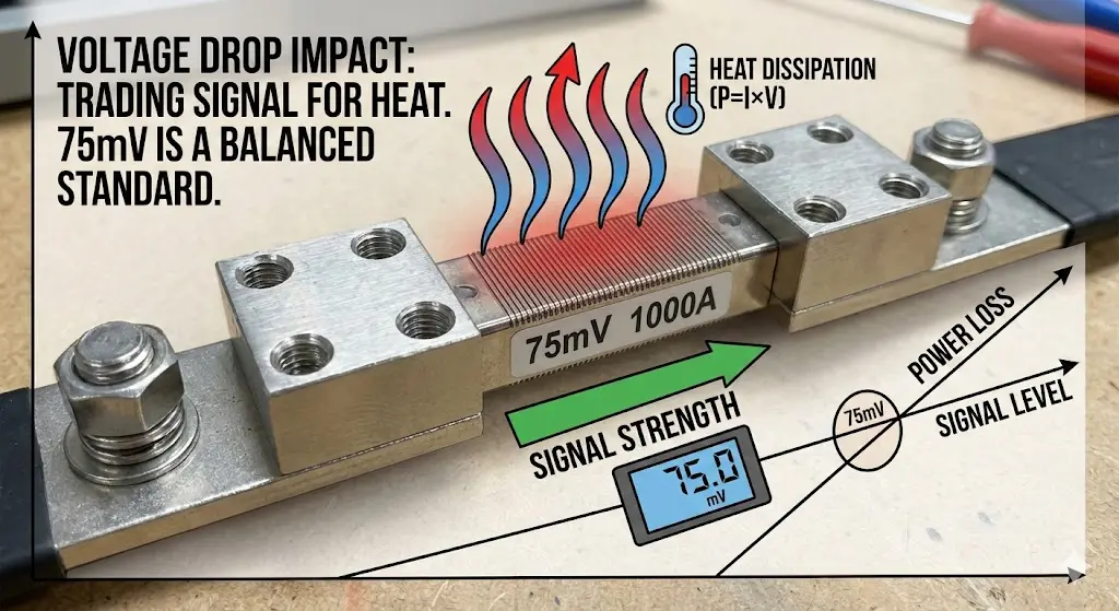
Understanding the trade-off between signal strength and power loss remains fundamental when choosing between 50mV, 75mV, or 100mV standards. A 75mV drop serves as the industry standard for most welding machines because it offers a balanced compromise: sufficient signal voltage for meters to read accurately without generating excessive waste heat. You might be wondering why manufacturers don’t always choose higher voltage drops for better signals. The answer lies in physics: higher voltage drop equals greater power dissipation (
). In a 1000A system, a 100mV shunt dissipates 100 Watts of heat, whereas a 50mV unit dissipates only 50 Watts. This extra heat requires larger heatsinks or active cooling, adding cost and bulk to your design.
High-noise environments found in heavy industrial plants often necessitate using 100mV or even higher rated shunts to override electrical interference. Large motors, variable frequency drives, and other welders create electromagnetic noise that can corrupt weak signals. Here’s the deal: a stronger 100mV signal provides a better signal-to-noise ratio, ensuring your controller reads actual current rather than background static. However, you must account for the increased thermal load. Calculating power loss is non-negotiable during the design phase. If you ignore this thermal calculation, your dc current shunt will overheat, causing resistance values to drift and eventually leading to element failure.
Voltage Drop Selection Strategy
| Voltage Drop | Signal Strength | Heat Generation | Best Application | |
|---|---|---|---|---|
| 50mV | Low | Low | Energy-efficient systems | |
| 75mV | Medium | Medium | Standard Welding Units | |
| 100mV | High | High | Noisy Industrial Plants |
4. Which dc current shunt accuracy class fits your specific process?
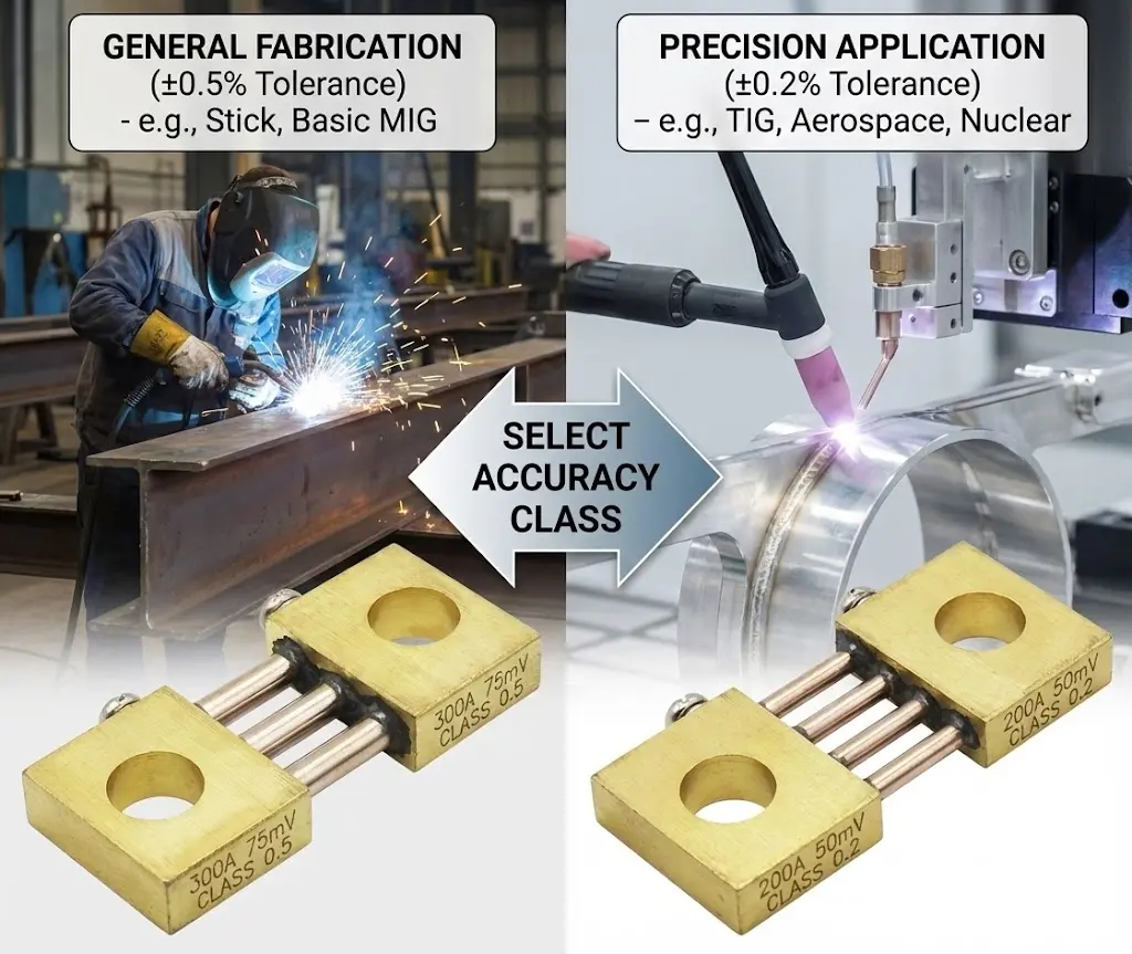
Class 0.5 accuracy typically suffices for general structural steel fabrication where minor current variations do not compromise structural integrity. This class guarantees that readings remain within ±0.5% of the rated value, providing a cost-effective solution for stick welders and basic MIG machines. It gets better: manufacturers can save significant budget by specifying Class 0.5 for non-critical paths. However, assuming this standard works everywhere is a mistake. When you move into automated processes or code-compliant work, tolerances tighten significantly. A 0.5% error at 500A equals 2.5A, which might be acceptable for a handrail but unacceptable for a pressure vessel root pass.
Class 0.2 becomes mandatory for aerospace, nuclear, and precision orbital welding applications where every amp counts. TIG welding exotic alloys like Titanium or Inconel requires exact heat input control to prevent metallurgical degradation. What’s the real story? investing in Class 0.2 precision prevents expensive rework. The tighter tolerance ensures that your actual output matches the digital display, allowing operators to trust their settings implicitly. You can find detailed specifications for these high-precision options on our Product Page . Balancing budget against performance requirements involves analyzing the cost of failure; if a bad weld costs thousands to fix, the premium for a high-accuracy dc current shunt pays for itself immediately.
Accuracy Class Applications
| Class | Tolerance | Recommended For | |
|---|---|---|---|
| 0.5 | ±0.5% | Stick, General MIG | |
| 0.2 | ±0.2% | TIG, Aerospace, Medical | |
| 0.1 | ±0.1% | Lab Calibration, R&D |
5. Can temperature coefficients alter dc current shunt performance?
Self-heating drift represents a silent killer of accuracy in welding applications that run for extended periods. As current flows through the resistive element, it generates heat, causing the material’s resistance to change slightly. You might be asking: why does my current reading drop after ten minutes of welding? This phenomenon occurs because inferior materials have high temperature coefficients. If resistance rises with heat, the voltage drop increases for the same current, causing your meter to read falsely high, or if resistance drops, the meter reads low. Your controller might then adjust output incorrectly, destabilizing the weld process. Manganin alloy is standard because its resistance remains stable across a wide thermal range.
Managing ambient welding environments adds another layer of complexity when equipment sits near pre-heated parts or furnaces. Key Takeaway: high ambient heat reduces the shunt’s ability to dissipate its own self-generated energy. You must consider derating the component—using a 500A shunt for a 300A application—to provide thermal headroom. Cooling strategies for continuous duty cycles often involve fan-forced air or mounting the dc current shunt on massive copper busbars that act as heat sinks. A low ppm/°C rating is non-negotiable for high-duty cycle automation; otherwise, your machine’s output will drift throughout the shift, resulting in inconsistent weld quality from morning to afternoon.
Temperature Management Strategies
| Issue | Cause | Solution | |
|---|---|---|---|
| Resistance Drift | Self-heating | Low ppm material (<50ppm) | |
| Overheating | High Ambient Temp | Derating (using larger shunt) | |
| Thermal Shock | Rapid Cycling | Robust mechanical design |
6. FL-19 Series: Is this the best dc current shunt for welders?
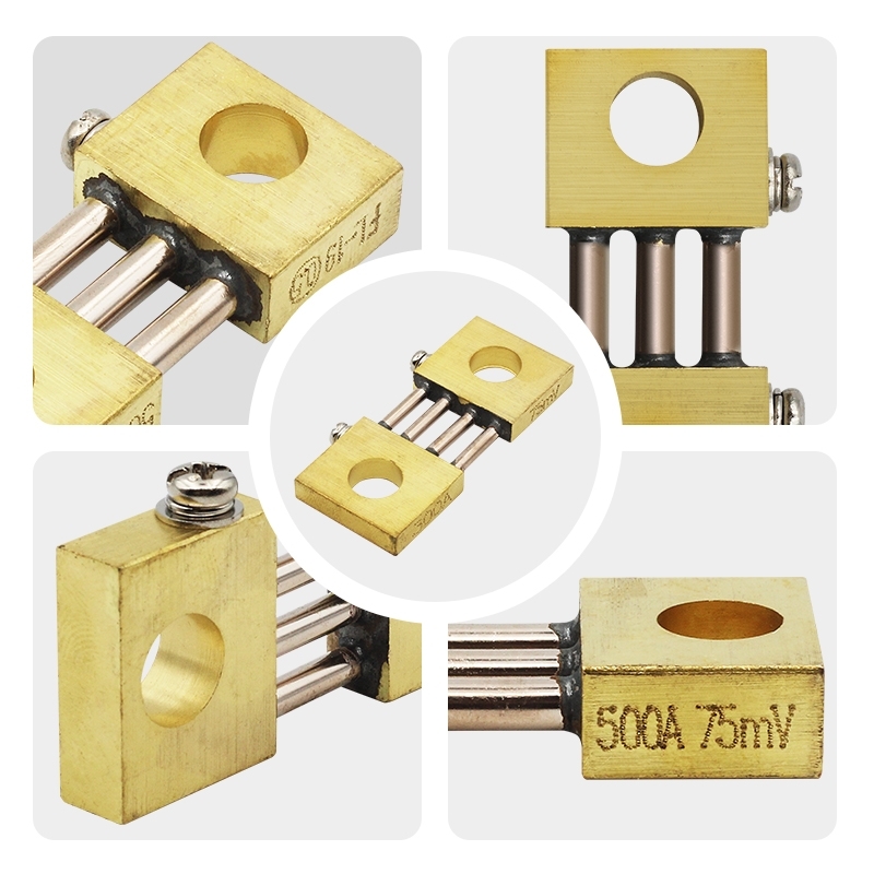
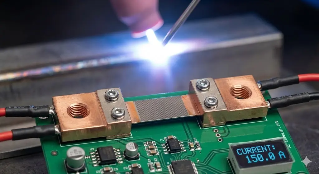
The FL-19 series is specifically designed to withstand the high-impact, variable load conditions found in welding. Unlike generic electronic shunts, the FL-19 features rugged construction capable of enduring the physical vibration and thermal shock typical of industrial floors. Here is the deal: standard shunts often fail mechanically before they fail electrically. The silver-brazed joints in the FL-19 ensure minimal contact resistance and maximum mechanical strength, preventing the resistive blades from separating from the copper blocks under stress. For detailed specs on this rugged series, check our DC Shunt Product Overview . This robustness makes it the preferred choice for mobile welding generators and heavy shop equipment.
Comparing the FL-19 to FL-US and FL-RU models reveals distinct advantages for different markets. But wait, there’s more: while FL-US models comply with American standards for dimensional interchangeability, FL-19 offers the best balance of cost and performance for general global welding applications. FL-RU models prioritize high-precision aesthetics and linearity, often used in laboratory-grade power sources. However, for the gritty reality of a shipyard or automotive plant, the FL-19’s resistance to dust, metal filings, and oil mist proves superior. Durability in harsh factory conditions ensures long-term reliability, reducing maintenance downtime and replacement costs for machine builders and end-users alike.
LEEYD Series Comparison
| Series | Primary Focus | Best Feature | |
|---|---|---|---|
| FL-19 | Welding | High vibration resistance | |
| FL-US | Standardization | US Spec Compliance | |
| FL-RU | Precision | Superior Linearity |
7. How to match a dc current shunt to high-power resistance welding?
Handling massive pulse currents typical of resistance spot welding involves dealing with spikes exceeding 10kA for mere milliseconds. Standard continuous ratings do not apply directly here because the duty cycle is low, but the peak intensity is enormous. What’s the real story? You cannot simply size for the average current; you must size for the peak pulse to prevent magnetic destruction. High currents create strong magnetic fields that exert physical torque on the parallel resistive blades. If the structure is weak, these forces warp the element, changing its calibration permanently. Reinforced mounting and robust blade design are mandatory requirements for any dc current shunt used in spot welding.
The “Derating” rule of thumb suggests sizing your component 20% to 30% above the peak expected surge to ensure thermal saturation never occurs. Key Takeaway: never run a shunt at 100% capacity in spot welding applications. Even though the pulse is short, the instantaneous heat generation is violent. A 10kA pulse generates 100 times the heat of a 1kA load (
I2R
law). Connecting these high-current devices requires massive busbars rather than cables to minimize contact resistance and heat buildup at the terminals. Proper integration ensures that your welding robot delivers consistent nuggets shift after shift without component fatigue.
High-Current Selection Guide
| Parameter | Requirement | Reason | |
|---|---|---|---|
| Rating | 120% of Peak | Prevents thermal saturation | |
| Structure | Reinforced | Resists magnetic torque | |
| Connection | Busbar | Minimizes contact resistance |
8. What are the installation risks for a welding dc current shunt?
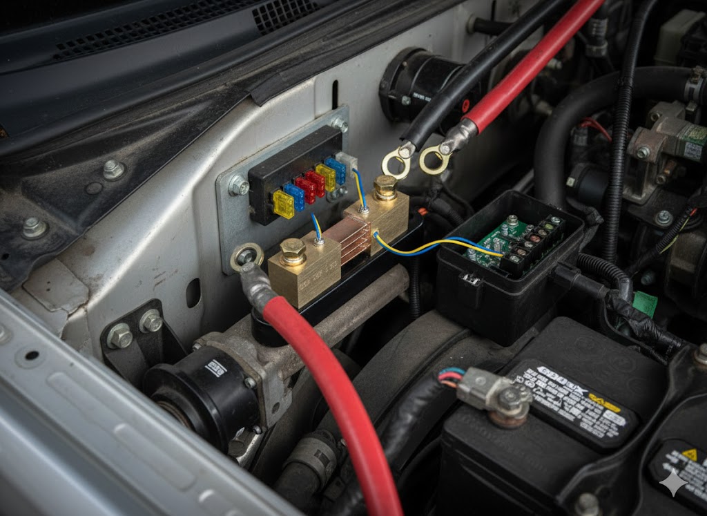
Correct torque application on current-carrying bolts prevents ninety percent of all field failures. A loose connection creates a high-resistance joint that generates localized heat intense enough to melt copper and destroy the resistive element. Ready for the good part? using a torque wrench during assembly solves this problem entirely. Manufacturers often overlook this simple step, relying on hand-tightening which varies by operator. Consistent torque values ensure optimal electrical contact pressure without stripping threads or crushing the material. Busbar alignment also plays a critical role; forcing a busbar into place introduces mechanical stress that can crack the manganin blades over time as the assembly heats and expands.
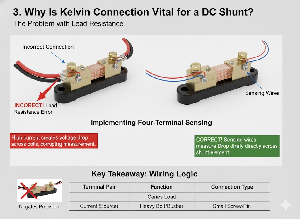
Signal wire placement utilizing a Kelvin connection is crucial for accuracy. You must connect the measurement wires to the small voltage screws located on the inner side of the shunt blocks, not to the large current bolts. Here is the kicker: connecting signal wires to the current bolts includes the contact resistance of the connection in your reading, introducing massive errors. Furthermore, shielding these signal wires from the welding arc’s electromagnetic interference is vital. Twisted pair cabling routes the millivolt signal safely to your controller, rejecting noise that would otherwise cause erratic behavior. Proper installation practices ensure your dc current shunt performs according to its accuracy class.
Installation Checklist
| Step | Action | Consequence of Failure | |
|---|---|---|---|
| Surface Prep | Clean & Sand | High contact resistance | |
| Mounting | Stress-free | Cracked element | |
| Wiring | Twisted Pair | Noisy signal data |
9. How do you identify signs of dc current shunt failure?
Recognizing drift and calibration loss often starts when the machine displays a set amperage, but the weld appearance suggests otherwise. If your display reads 200A but the puddle looks cold and penetration is shallow, your feedback loop is likely lying. This is where it gets interesting: resistance drift is usually the first silent killer before total failure occurs. Physical signs of thermal stress include visible discoloration on the copper blocks, turning them purple or blue. This “bluing” indicates that the copper reached temperatures exceeding 250°C, permanently annealing the metal and altering the resistive alloy’s properties.
Micro-cracks in the resistive blades can result from vibration or thermal shock, causing intermittent open circuits or fluctuating readings. Key Takeaway: regular visual inspection saves downtime. Troubleshooting signal noise issues involves distinguishing between a failing component and ground loop interference. If the reading jumps erratically only when the arc starts, suspect noise or grounding; if the reading is stable but wrong, suspect the shunt. For more troubleshooting tips, refer to our Selection and Maintenance Guide . Identifying these signs early allows for proactive replacement before a catastrophic line stoppage occurs.
Troubleshooting Guide
| Symptom | Probable Cause | Action | |
|---|---|---|---|
| Discoloration | Overheating | Check connections/load | |
| Erratic Reading | Loose Signal Wire | Re-torque screws | |
| Zero Reading | Open Circuit | Replace shunt |
10. How does digital feedback improve dc current shunt accuracy?
Integrating analog shunts with digital controllers moves welding technology from simple needle gauges to sophisticated logic systems. You might be wondering: can old analog technology truly work with modern digital interfaces? Absolutely. The shunt provides the raw analog voltage data, which high-resolution analog-to-digital converters (ADCs) then process. This combination allows for features like peak hold, data logging, and predictive analytics. Real-time data monitoring benefits production managers by tracking current trends over weeks, identifying slow drifts that signal impending equipment maintenance before a breakdown happens.
Adapting analog shunts for IoT environments enables remote monitoring of entire factory floors. But wait, there’s more: smart welding cells now compare real-time shunt data against ideal waveform models stored in the cloud. If the current profile deviates from the golden standard, the system alerts maintenance instantly. While Hall effect sensors offer an alternative, the dc current shunt remains the gold standard for linearity and zero-drift performance in these digital loops. Shunts provide the uncorrupted raw data that makes smart, connected welding possible, bridging the gap between heavy iron hardware and silicon intelligence.
Analog vs. Digital Integration
| Feature | Analog System | Digital System | |
|---|---|---|---|
| Response | Instant | Processed/Logged | |
| Readout | Gauge Needle | HMI Screen | |
| Features | Simple View | Data Analysis/IoT |
Conclusion
From the delicate precision of micro-TIG work to the brute force of industrial spot welding, your choice of dc current shunt dictates the quality of every weld you produce. We explored how current ranges, voltage drops, and thermal coefficients all play critical roles in system stability. Don’t let a generic component compromise your engineering reputation or production efficiency.
Ready to upgrade your welding precision? At LEEYD, we engineer stability into every component. Whether you need a standard FL-19 or a custom high-current solution, our team stands ready to support your project with certified expertise. Contact us today to discuss your specifications or request a quick quote.
FAQ Section
Q1: What is the ideal DC shunt model for general TIG welding?For TIG welding applications, the FL-19 series is highly recommended. We typically suggest a Class 0.5 or Class 0.2 accuracy rating with a current rating approx 20% higher than your max output (e.g., a 250A shunt for a 200A machine) to ensure precision and thermal headroom.
Q2: How does material thickness affect the current requirement for my shunt?As a rule of thumb, you need approximately 1 Amp of current for every 0.001″ of steel thickness. Thicker materials or conductive metals like aluminum require higher amperage, meaning your dc current shunt must be rated to handle these increased continuous loads without overheating.
Q3: Can I use a 75mV shunt if my system was designed for 50mV?Generally, no. Swapping voltage drops (e.g., 50mV to 75mV) without recalibrating your metering equipment will result in incorrect readings. A 75mV shunt will send a stronger signal than a 50mV shunt at the same amperage, causing your meter to read 50% higher than the actual current.
Q4: Why is my DC shunt getting discolored?Discoloration (often purple or blue hues on the copper) indicates overheating. This is usually caused by loose electrical connections creating high resistance, or by running the shunt constantly above its rated capacity. It is a sign of thermal stress and suggests the unit should be inspected or replaced.
Q5: How often should a welding DC shunt be calibrated?While the shunt itself is a fixed resistor, the system should be verified annually. In heavy-duty welding environments involving vibration and thermal cycling, we recommend a visual inspection for physical damage every 6 months to ensure the dc current shunt maintains its Class accuracy.