Problem: Monitoring high amperage in direct current systems presents a unique challenge for electrical engineers and facility managers. Standard multimeters cannot handle the massive load, and direct connection often leads to equipment failure or safety hazards. Agitate: Imagine your critical power backup going offline because a sensor burned out during a surge. 30 seconds too long. And it’s ruined. That downtime costs thousands in lost production and hardware replacement. Solution: Using a dc current shunt offers a safe, precise bridge between high-power loads and sensitive monitoring instrumentation. Trust: We engineer stability into every component, ensuring your power systems deliver reliable data when it matters most.
1. How does a dc current shunt function?
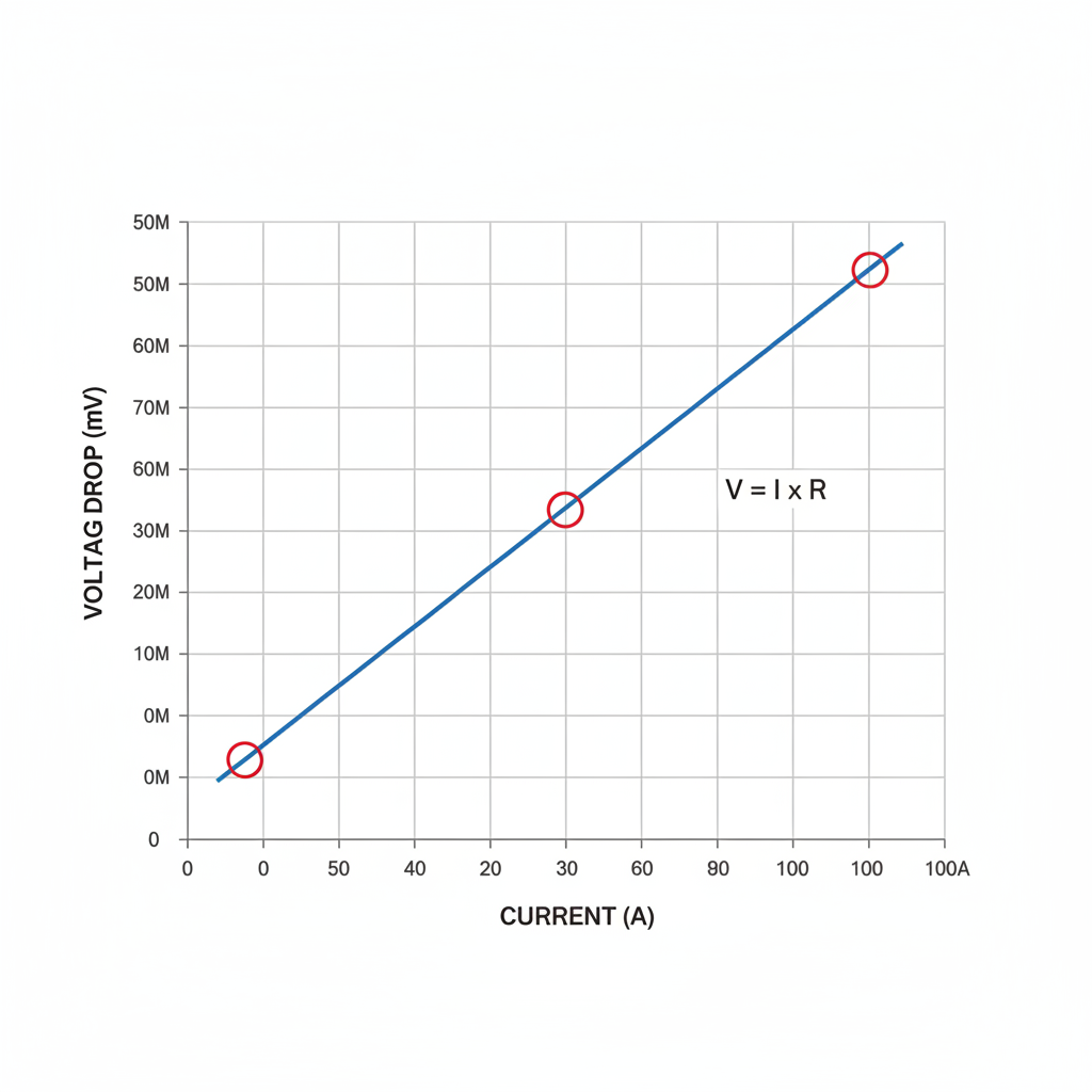
A dc current shunt operates by creating a precise, low-resistance path for electric current while generating a proportional voltage drop. This passive component follows Ohm’s Law rigidly, where the voltage across the terminals equals current multiplied by resistance. By installing our high-precision dc current shunt in series with the load, you convert dangerous high amps into a safe millivolt signal. Meters then read this low-voltage signal and scale it to display the actual amperage. This method allows standard panel meters to monitor thousands of amps without direct exposure to the main busbar energy. It provides the foundation for control systems in everything from heavy industry to renewable energy grids.
The Voltage Drop Principle
Here’s the deal: The shunt acts as a transducer. As electrons flow through the resistive element, they encounter a specific amount of opposition. This resistance forces a small potential difference between the two sensing terminals. Manufacturers calibrate this drop typically to 50mV or 75mV at full rated current. A 100A shunt rated for 50mV will produce exactly 0.5mV per Amp flowing through it. You rely on this linear relationship for accuracy.
Calculating Current from Voltage
You might be wondering, how does the meter know the amp value? The meter measures only voltage but displays amps based on a programmed ratio. If your system uses a 500A/50mV shunt, the ratio is 10 Amps per millivolt. A reading of 25mV instantly tells you that 250 Amps flows through the circuit. This simple calculation eliminates complex electronics in the high-power path.
Key Takeaway: Fundamental Operation
| Parameter | Value | Description | |
|---|---|---|---|
| Formula | V=I×R | Voltage equals Current times Resistance. | |
| Standard Output | 50mV / 75mV | Common full-scale voltage drops. | |
| Function | Transducer | Converts Amps to Millivolts. | |
| Linearity | High | Linear output across operating range. |
Analysis: The fundamental reliability of a shunt comes from its purely resistive nature, eliminating active electronic failure points.
2. Why is manganin material used in a dc current shunt?
Manganin serves as the industry standard for precision shunts because it possesses a near-zero temperature coefficient of resistance (TCR). Ordinary metals like copper increase their resistance drastically as they heat up, which would skew your measurement data significantly under load. A specific alloy of copper, manganese, and nickel, Manganin remains stable even as current drives the temperature higher. This stability ensures that your readings remain consistent whether the system is cold or running at full capacity. Without this specialized material, thermal drift would render high-current measurement practically useless for control applications.
The Temperature Coefficient Advantage
What’s the real story? Copper changes resistance by roughly 0.39% for every degree Celsius rise. That sounds small, but a 50°C rise creates a 20% error. Manganin, by contrast, shifts only about 0.002% per degree. You get accurate data regardless of the operating environment. This property makes it indispensable for instrumentation where precision determines safety.
Manganin vs Copper Construction
But here’s the kicker: You cannot use Manganin for the entire device. Manganin blades are brazed or electron-beam welded into copper mounting blocks. The copper blocks handle the high-current connection to your busbars with minimal loss. The Manganin blades in the center perform the actual measurement. This hybrid construction balances conductivity with measurement precision.
Key Takeaway: Material Properties
| Material | Composition | TCR (ppm/°C) | Application | |
|---|---|---|---|---|
| Manganin | Cu-Mn-Ni | ±15 | Precision Sensing | |
| Copper | Pure Cu | +3900 | High Current Conductor | |
| Brass | Cu-Zn | +1500 | Mounting Blocks | |
| Constantan | Cu-Ni | ±20 | General Purpose |
Analysis: Manganin’s metallurgical stability is the singular reason shunts can maintain 0.25% accuracy across wide temperature ranges.
3. How does high heat affect a dc current shunt?
Excessive heat acts as the primary enemy of accuracy and longevity in any resistive measurement device. While our industrial power systems components can withstand significant thermal stress, running a shunt above 80°C (176°F) begins to compromise its precision. Extreme temperatures can permanently alter the crystalline structure of the manganin alloy, causing a lasting shift in resistance values. This “annealing” effect means your meter will never read zero correctly again. You must manage thermal loads through proper sizing and airflow to protect the integrity of your measurement data.
Maximum Safe Operating Limits
This is where it gets interesting: Ratings on the datasheet often mislead new users. A shunt might list an operating range up to 140°C, but that represents a survival limit, not an accuracy limit. For precision class 0.5 or better, you should keep the element below 80°C. Exceeding this threshold causes the resistance curve to bend, introducing non-linear errors.
Derating for Longevity
Ready for the good part? You can prevent overheating easily by applying the “2/3 Rule”. Select a shunt rated for 150% of your expected continuous load. If your system draws 100A continuously, install a 150A unit. This extra mass dissipates heat more effectively. Vertical mounting also helps by allowing natural convection to pull heat away from the blades.
Key Takeaway: Thermal Derating
| Ambient Temp | Load Factor | Action Required | |
|---|---|---|---|
| 25°C | 100% | Normal Operation | |
| 60°C | 80% | Derate Load | |
| 80°C | 60% | Critical Limit | |
| >100°C | 0% | Unsafe / Permanent Damage |
Analysis: Heat management is not just about preventing failure but preserving the calibrated accuracy of the manganin element.
4. How to properly install a dc current shunt?
Installation quality directly dictates the mechanical safety and electrical accuracy of the final system. You must mount the shunt on a flat surface to prevent mechanical stress on the resistive blades. Bending or twisting the block can fracture the brazed joints or alter the resistance. Furthermore, the shunt belongs on the grounded (negative) leg of the circuit. This “low-side” sensing keeps the voltage potential at the meter close to ground, protecting personnel from shock. Ignoring these mechanical constraints often leads to cracked elements or dangerous hot spots at connection points.
Managing Physical Stress
You might be wondering, why do shunts break mechanically? Heavy busbars expand and contract as they heat up. If you bolt a rigid busbar directly to both ends of the shunt, that thermal expansion forces the shunt to bend. You should always use a flexible braided strap or expansion loop on at least one side. This absorbs the movement and isolates the precision element from mechanical force.
Torque and Surface Prep
Here’s the deal: High current demands perfect contact. Oxidation on the mounting surface creates resistance, which generates heat. Clean all mating surfaces until they shine before installation. Apply the manufacturer’s specified torque to the large bolts. Loose bolts cause arcing and fire, while overtightening can strip the copper threads.
Key Takeaway: Installation Checklist
- Orientation: Blades vertical for cooling.
- Konum: Negative (return) line.
- Mounting: Flat surface, no twisting.
- Connection: Flexible link on one side.
Analysis: Mechanical isolation using flexible links prevents thermal expansion forces from physically destroying the precision resistor.
5. How to wire a meter to a dc current shunt?
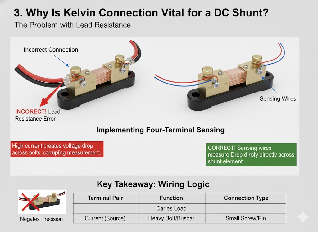
Wiring a meter requires a specific four-wire configuration known as a Kelvin connection. Two large cables carry the main system current, while two smaller wires carry the measurement signal to the meter. You must connect your meter sensing wires only to the small screws provided on the shunt block. Connecting them to the large bolts introduces significant error because it includes the contact resistance of the main lug. For our custom electrical products , this separation is non-negotiable for achieving the rated 0.5% accuracy.
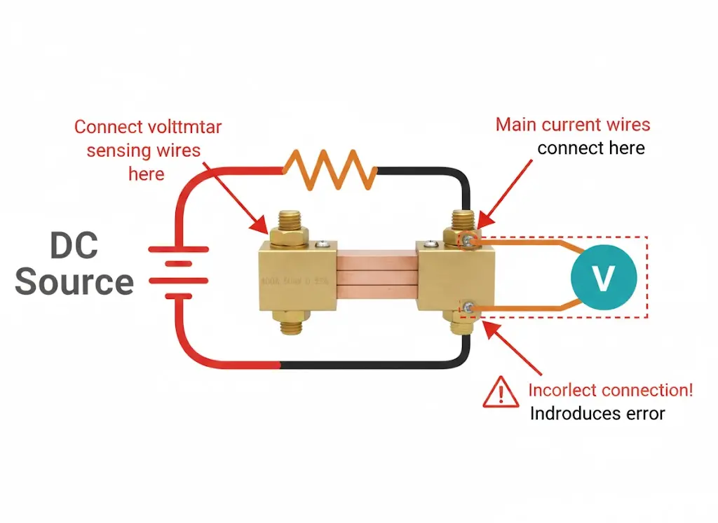
The Kelvin Connection Explained
What’s the catch? Voltage drops everywhere current flows. The connection between your heavy cable and the shunt block has resistance. If you measure across the large bolts, you measure the shunt plus that messy contact resistance. The small screws tap into the manganin element directly, inside the high-current path. This bypasses the noisy connections entirely.
Why Separation Matters
But here’s the kicker: The voltage drop across a loose bolt can exceed the 50mV signal of the shunt itself. Your meter could read double the actual current if wired incorrectly. By using the dedicated sensing screws, you ensure the meter sees only the clean voltage drop generated by the precision resistor. This is the secret to laboratory-grade accuracy in the field.
Key Takeaway: Wiring Logic
| Terminal | Wire Gauge | Connects To | Signal Type | |
|---|---|---|---|---|
| Large Bolt A | 4/0 AWG+ | Battery Neg | High Current | |
| Large Bolt B | 4/0 AWG+ | Load Neg | High Current | |
| Small Screw 1 | 16-20 AWG | Meter (+) | 0-50mV Signal | |
| Small Screw 2 | 16-20 AWG | Meter (-) | 0-50mV Signal |
Analysis: The Kelvin connection is the only physical way to isolate the sensing signal from the variable contact resistance of high-power connections.
6. How does lead resistance impact a dc current shunt?
Lead resistance becomes a critical factor when using analog panel meters with your shunt. Unlike digital meters, which have high input impedance, analog meters draw a small amount of current from the shunt to move the needle. The resistance of the wires connecting the shunt to the meter reduces the voltage available to drive the mechanism. If your wires are too long or too thin, the meter will read lower than the actual value. You must calculate wire gauge carefully or calibrate the meter for the specific lead length used in your installation.

Analog vs Digital Sensitivity
This is where it gets interesting: Digital meters usually ignore lead resistance. Their input impedance often exceeds 1 Mega-ohm, meaning almost zero current flows through the sense wires. No current means no voltage drop. However, if you use a classic analog needle gauge, it acts as a load. Even 0.1 ohms of wire resistance can introduce a 1% to 2% error in the reading.
Calibrating Out the Error
Ready for the good part? You can fix this easily. Most analog meters come calibrated for a specific lead resistance, typically 0.065 ohms. If you need 50 feet of wire, use a thicker gauge (like #14 AWG) to keep the total resistance down to that value. Alternatively, order a meter with a customized internal calibration resistor to match your exact wire run.
Key Takeaway: Resistance Impact
| Meter Type | Input Impedance | Lead Effect | Solution | |
|---|---|---|---|---|
| Digital | >1 M | Negligible | Use any standard wire. | |
| Analog | <50 | Significant | Use calibrated leads. | |
| Data Logger | >10 M | None | Twisted pair recommended. |
Analysis: While digital systems largely eliminate this issue, legacy analog systems require strict adherence to maximum lead resistance values.
7. When to add a signal conditioner to a dc current shunt?
A signal conditioner is necessary when you need to transmit the current reading over long distances or into a PLC control system. The raw 50mV output from a shunt is too weak to survive hundreds of feet of cable without interference. Electrical noise from motors and relays can easily corrupt such a small signal. By contacting our technical support team , you can integrate an isolator that amplifies the tiny millivolt drop into a robust 4-20mA or 0-10V signal. This ensures your control room receives clean, accurate data regardless of the electrical noise in the environment.
Amplifying for Distance
You might be wondering, why use 4-20mA? A current loop signal does not degrade over distance like a voltage signal does. If you run a 50mV signal wire 100 meters, resistance drops the voltage to nothing. A 4-20mA current loop forces the signal through the wire regardless of resistance. It guarantees the data arrives intact.
Protection and Isolation
Here’s the deal: Direct connection to a high-power busbar exposes your delicate PLC to potential ground loops. If the ground potential at the shunt differs from the PLC ground, you could fry the input card. A signal conditioner provides galvanic isolation. It separates the high-voltage side from the low-voltage logic side, preventing catastrophic equipment damage.
Key Takeaway: Conditioner Benefits
| Feature | Benefit | Typical Use | |
|---|---|---|---|
| Amplification | Boosts mV to V/mA | Long cable runs. | |
| Isolation | Breaks ground loops | PLC / SCADA interface. | |
| Filtering | Removes noise | VFD / Motor environments. | |
| Standardization | Common inputs | Integrating diverse sensors. |
Analysis: Signal conditioners bridge the gap between raw physical measurement and sophisticated digital control systems.
8. How to select the correct dc current shunt rating?
Selecting the right rating requires balancing the maximum current capacity against the desired signal resolution. A common mistake involves choosing a shunt rated exactly for the peak load. This leads to overheating during continuous operation. We recommend sizing the shunt so your continuous load represents no more than 66% of its rating. For systems with high surge currents, like motor starters, you need a unit that handles the peak without saturation while providing good resolution at idle.
Continuous vs Peak Current
What’s the real story? Shunts heat up over time. A 100A shunt can handle 100A for a few minutes, but it will get too hot for accuracy if run for hours. Sizing it at 150A for a 100A load keeps it cool. However, do not oversize too much. A 1000A shunt measuring 10A produces a signal so tiny (0.5mV) that noise will drown it out.
Choosing Voltage Drop
But here’s the kicker: You usually have a choice between 50mV and 100mV models. A 50mV shunt generates less heat (
P=I×V
) and disturbs the circuit less. A 100mV shunt provides double the signal strength, which helps with accuracy in noisy environments. For most standard industrial panels, the 50mV version offers the best balance of thermal performance and signal quality.
Key Takeaway: Selection Guide
| Load Type | Sizing Rule | Recommended Drop | |
|---|---|---|---|
| Continuous | 1.5× Max Load | 50mV (Less Heat) | |
| Intermittent | 1.2× Peak Load | 75mV (Better Signal) | |
| Precision | 2.0× Max Load | 100mV (High Resolution) | |
| Motor Start | 1.0× Surge | 50mV (Standard) |
Analysis: Proper sizing trades a small amount of low-end resolution for significant gains in thermal stability and component lifespan.
9. How to troubleshoot errors in a dc current shunt?
Troubleshooting usually reveals that the shunt itself works fine, but the connections have failed. Being a passive chunk of metal, a shunt rarely fails unless physically melted. Errors typically stem from loose connection bolts, corrosion, or incorrect wiring of the sense leads. When users report “drifting” readings, it often points to a thermal issue caused by a bad joint heating up the entire block. Our instruments and accessories support team often advises checking torque specs first.
Detecting the “Hot Spot”
This is where it gets interesting: A loose bolt creates resistance. Resistance creates heat. If one side of your shunt glows hot on a thermal camera, you have a bad connection, not a bad shunt. This heat conducts into the manganin, ruining the accuracy. Tightening the bolts often solves “calibration” errors instantly.
Verifying with a Multimeter
Ready for the good part? You can verify a shunt in seconds. Put a multimeter (set to mV DC) on the two small screws. Measure the drop while the load runs. If the meter reads 25mV on a 50mV/100A shunt, then 50A is flowing. If your panel meter says 0A but your multimeter says 25mV, the panel meter or wiring is broken. If both read 0mV, no current flows.
Key Takeaway: Troubleshooting Matrix
| Symptom | Likely Cause | Fix | |
|---|---|---|---|
| Drifting Value | Overheating | Check ventilation / bolts. | |
| Reading = 0 | Open Fuse / Wire | Check sense lead continuity. | |
| Reading Low | High Lead Res | Shorten wires / Recalibrate. | |
| Reading High | Wrong Ratio | Check meter programming. |
Analysis: Ninety percent of shunt “failures” are actually installation failures involving torque, cleanliness, or wiring logic.
10. What are the key applications of a dc current shunt?
Shunts serve as the heartbeat of modern DC infrastructure, from renewable energy to heavy transportation. In battery energy storage systems (BESS), they track the state of charge by counting every coulomb entering and leaving the cells. In telecommunications, they ensure rectifiers share the load equally to prevent burnout. These simple components enable the complex logic that keeps green energy grids stable and electric vehicles moving.

Renewable Energy and Storage
You might be wondering, how does my solar inverter know when to clip power? A shunt on the DC input provides real-time feedback. If current exceeds the limit, the controller adjusts the voltage. For batteries, the shunt provides the “fuel gauge” data, integrating amps over time to calculate remaining capacity percent.
Heavy Industry and Plating
Here’s the deal: Electroplating requires exact amperage to deposit metal at the right thickness. A fluctuation of 5% can ruin a production batch. Large 10,000A shunts sit on the rectifier output, feeding precise control loops that regulate the process. This ensures uniform quality in galvanizing and anodizing lines.
Key Takeaway: Application Table
| Sector | Application | Function | |
|---|---|---|---|
| Solar / Wind | Inverter Control | Power optimization. | |
| EV / Battery | BMS | State of Charge (SoC). | |
| Telecom | Rectifiers | Load sharing. | |
| Industrial | Plating / Welding | Process regulation. | |
| Marine | Distribution | Power management. |
Analysis: Wherever DC power moves in significant quantities, a shunt provides the essential visibility required for control and safety.
Conclusion
The dc current shunt remains the most robust solution for measuring high-power direct current. Its passive design delivers reliability that complex sensors cannot match, provided you respect the thermal and mechanical rules of installation. From selecting the right manganin alloy to ensuring a proper Kelvin connection, every detail matters for accuracy.
Take the next step: Do not let poor measurement jeopardize your expensive infrastructure. Secure your power systems with components built for precision.
Contact us today to discuss your specific requirements or explore our full range of shunt solutions.
SSS
Q1: Can I mount a shunt in any position?No, you should ideally mount the shunt with the blades oriented vertically. This position promotes natural convection cooling, allowing air to flow up through the blades. Mounting it horizontally traps heat, which can lead to accuracy drift or overheating.
Q2: What happens if I use a 75mV meter with a 50mV shunt?The meter will read incorrectly, specifically lower than the actual value. If 100A flows through a 50mV shunt, it generates 50mV. The 75mV meter expects 75mV for full scale (100A). Seeing only 50mV, it will display 66.6A. You must match the voltage rating exactly.
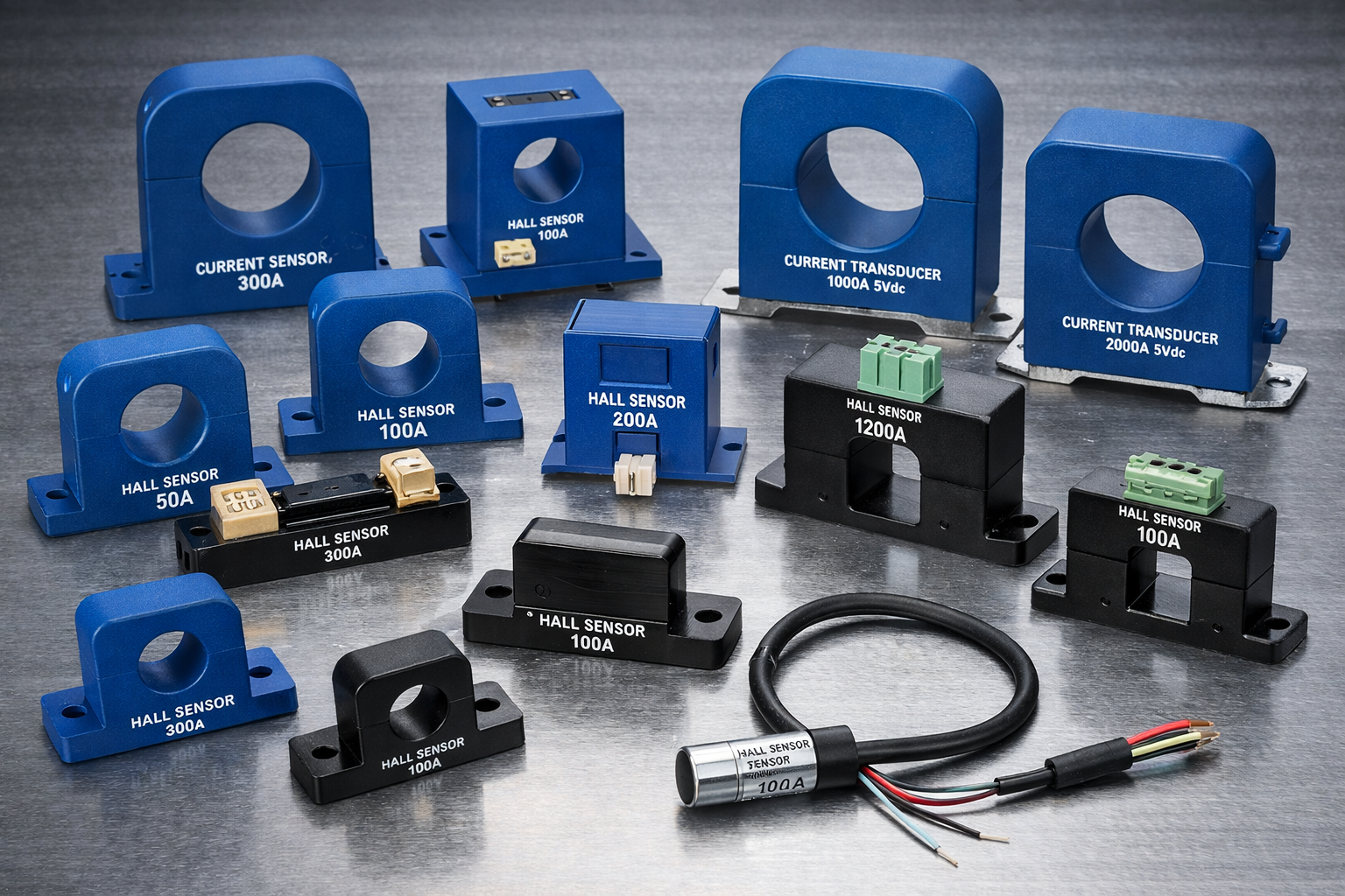
Q3: How do I choose between a shunt and a Hall effect sensor?Use a shunt when you need high accuracy (0.25%) and simplicity at a lower cost, especially for stable DC currents. Choose a Hall effect sensor if you need total galvanic isolation or if you are measuring AC and DC mixed signals, though they often drift more over time.
Q4: Can I extend the sense wires on my shunt?Yes, but with caution. If using a digital meter, you can extend them significantly without issue. If using an analog meter, extending wires adds resistance that will lower the reading. You may need to use thicker wire or recalibrate the meter to compensate for the added length.
Q5: Why does my shunt look discolored?Discoloration, usually darkening of the manganin or copper, indicates overheating. This happens if the connections are loose or if the shunt is undersized for the load. If the metal turns blue or black, the resistive properties may have permanently changed, and you should replace the unit.