Technical Solution Series | Last Updated: March 16, 2026
In industrial DC systems, an ammeter is not just a display device. It affects how accurately you monitor load current, how early you detect overload conditions, and whether your meter and shunt can operate safely under continuous heat. For buyers and engineers, the real challenge is usually not understanding “what an ammeter is,” but how to match the meter type, shunt output, accuracy class, and installation method to the actual application to avoid costly equipment downtime.
To ensure your system’s long-term integrity, we focus on three technical pillars of what is an ammeter:
- Environmental Selection: Choosing between analog resilience for high-EMI sites and digital precision for SCADA integration.
- System Compatibility: Matching the meter’s full-scale input to the specific millivolt (mV) output of the DC current shunt.
- Thermal Management: Calculating power dissipation (I²R) in shunts to prevent reading drift and enclosure overheating.

Understanding the Basics: How an Ammeter Quantifies Current in Industrial Loops
An ammeter is used to measure current in a circuit, but in industrial systems, its value lies in how reliably it reflects actual load conditions over time. Whether the meter is analog or digital, the goal remains the same: capturing current data without introducing a significant voltage drop or system instability.
In many panel meter applications, direct measurement is practical only at lower current ranges (typically under 20A–50A depending on the internal coil design). Once the system current moves beyond the meter’s direct input capability, an external DC current shunt becomes mandatory.
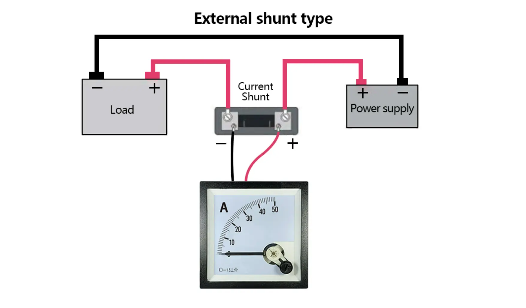
Why Series Connection is a Non-Negotiable Safety Protocol We must emphasize a critical installation rule: Ammeters (or their shunts) must always be connected in series with the load. Because an ammeter is designed with near-zero internal resistance to avoid interfering with the circuit, connecting it in parallel—like a voltmeter—across a power source will cause a dead short circuit. In high-voltage industrial DC systems, this mistake leads to the immediate melting of the internal shunt or catastrophic failure of the sensing terminals.
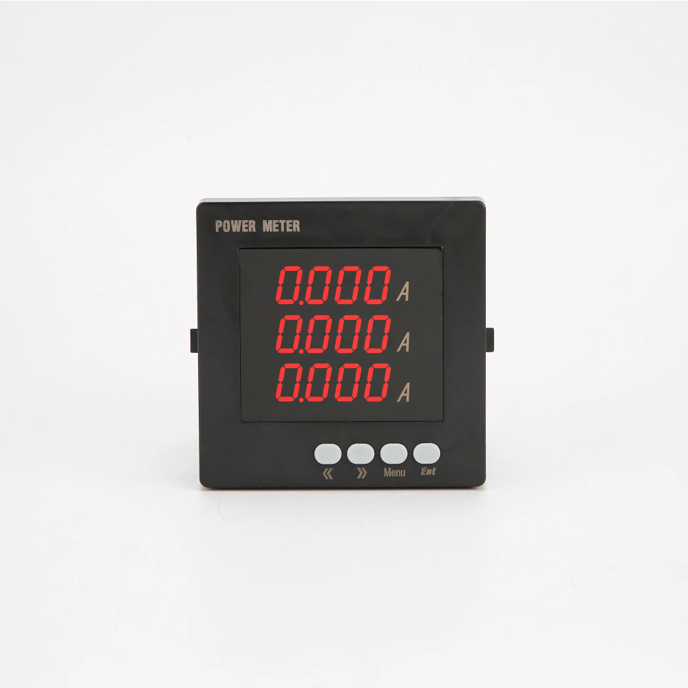
Analog vs. Digital Ammeters: Application-Based Selection
Instead of asking which technology is “better,” you should evaluate based on your specific panel meter environment. Analog meters are still preferred in harsh environments where simple local indication is valued and auxiliary power is limited, while digital units excel in data-driven automation.
Decision Matrix for Engineering Selection
| Scenario | Better Choice | Engineering Logic |
| Local Panel Indication Only | Analog | Passive (self-powered); provides “at-a-glance” trend monitoring. |
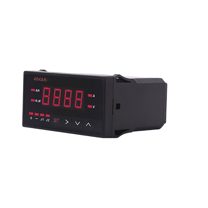
| PLC / SCADA Integration | Digital | Supports Modbus RTU or 4-20mA outputs for remote logging. |
| High EMI / VFD Proximity | Analog | Mechanical inertia acts as a natural filter against high-frequency noise. |
| High Vibration / Mining | Digital | No moving parts to drift or get stuck under constant mechanical stress. |
| Motor Inrush Monitoring | Analog | The needle provides a visual average of spikes that digital digits can’t track. |
The Accuracy Trap: Class 0.5 vs. Class 1.5
In B2B procurement, understanding the accuracy class is vital to avoid measurement uncertainty. A Class 1.5 rating indicates that the maximum permissible error is fixed at 1.5% of the full-scale value.
For a 1000A/1.5 ammeter, the allowable deviation is $\pm 15A$ across the entire scale. If you attempt to measure a 100A load with this meter, that fixed 15A margin represents a potential 15% relative error compared to your actual reading—rendering the data practically useless for precision monitoring. To maximize your “Signal-to-Error” ratio, we recommend sizing the ammeter so that your normal operating current falls within the upper 2/3 of the scale (typically 50% to 85%), where the fixed error has the least impact on your data integrity.
Scaling for Industry: Why the DC Current Shunt is Mandatory
In standard laboratory settings, ammeters often handle current directly. However, in industrial power distribution, renewable energy storage (BESS), or EV charging infrastructure, currents frequently reach 500A, 1000A, or higher. No standard meter movement can survive these loads without vaporizing internal components. This is where the Shunt-Based Measurement principle becomes critical for system design.
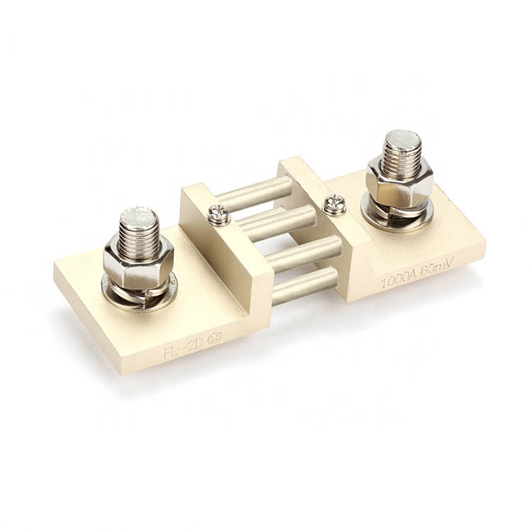
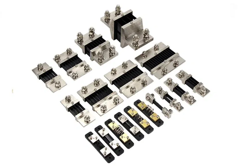
The Engineering Logic of Shunt Integration A DC current shunt is a high-precision, low-resistance resistor connected in series with the load. It acts as a “bypass” that allows the vast majority of current to pass through its robust manganin alloy body, while dropping a predictable millivolt signal (typically 75mV) for the ammeter to read.
Example: Why Shunt Heat Management Matters Let’s look at the math for a 1000A / 75mV shunt:
- Resistance Calculation: 0.075V / 1000A = 0.000075 Ohm
- Power Loss at Full Load (P = I^2 * R): 1000^2 * 0.000075 = 75 Watts
75 Watts of heat dissipation is equivalent to an old-school incandescent bulb burning inside your cabinet. If the shunt is mounted in a sealed enclosure without a 10cm ventilation buffer, the resulting temperature rise will trigger Reading Drift as the alloy’s resistance changes with heat. For long-term reliability, we recommend a “Continuous Loading Rule”: ensure the continuous operating current does not exceed 80% of the shunt’s rated capacity to allow for a thermal safety margin.
Installation & Commissioning: Eliminating Measurement Errors
Integrating an ammeter into an industrial cabinet requires more than just basic electrical knowledge; it demands precision in wiring to avoid signal noise and hardware failure. In our experience, the most common measurement discrepancies are not caused by the meter itself, but by poor installation practices.
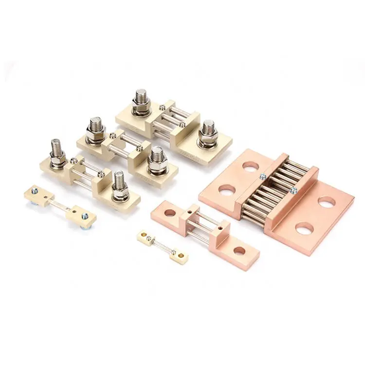
The 4-Wire Kelvin Connection: A Non-Negotiable Standard
One of the most frequent errors we see in the field is using the primary load bolts for signal sensing. Always use a 4-wire Kelvin connection. Connect your heavy-gauge copper busbars to the large primary terminals of the DC current shunt, but take your meter signal leads from the smaller potential terminals. This bypasses the contact resistance of the main lugs, which can otherwise cause the ammeter to read 5% to 10% higher than the actual current.
Common Failure Modes and Verification
| Symptom | Likely Root Cause | Engineering Verification |
| Negative Reading | Reversed Sensing Leads | Verify that the “Meter +” is connected to the shunt terminal closest to the power source. |
| Erratic/Jumping Digits | EMI / Signal Interference | Check if sensing wires share a cable tray with VFD output cables; replace with shielded twisted pair (STP). |
| Reading Drifts Over Time | Thermal Overloading | Verify the 10cm clearance rule and check for loose terminal torque causing local hotspots. |
| Stable Zero Drift | Transit Vibration | For analog meters, adjust the mechanical zero-point screw on the front bezel. |
Final Procurement Checklist: Ensuring a High-ROI Selection
Before finalizing your purchase order for an ammeter and its matching shunt, use this engineering checklist to avoid common integration pitfalls. A mismatch in these parameters is the leading cause of field rework and system downtime.
- Signal Matching: Does the meter’s full-scale input (e.g., 75mV) match the shunt output exactly?
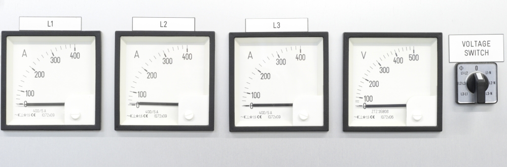
- Scale Calibration: For analog meters, is the dial plate printed to match your primary current (e.g., a 500A scale for a 500A shunt)?
- Mounting Clearance: Is there at least 10cm of air space around the shunt for convection cooling?
- Terminal Material: Are the terminals solid brass or copper to minimize contact resistance and heat soak?
- Environment Fit: Does the panel cutout (e.g., 96x96mm or 72x72mm) and rear-depth clearance fit your cabinet layout?
- Auxiliary Power: For digital meters, is the power supply (24VDC, 110VAC, etc.) compatible with your control bus?
Conclusion: Beyond Data, Securing Infrastructure Integrity
In practice, most current measurement failures do not stem from the meter alone. They result from mismatched shunt outputs, unrealistic continuous loading, or an installation environment that was overlooked during the procurement phase.
Whether you prioritize the uncompromising reliability of an analog display or the high-fidelity data integration of a digital system, your choice of ammeter must align with the full measurement chain. By integrating a precision-matched 75mV shunt with a robust meter and following the 80% loading rule, you secure not just data, but the long-term integrity of your electrical infrastructure.
FAQ
Q1: How do I determine if a project requires a direct-insert ammeter or a shunt-based system? Answer: The decision depends on the continuous current load and thermal safety. Direct-insert ammeters are typically designed for lower ranges (up to 20A or 50A). However, in industrial panels, running high current directly through the meter generates localized heat that can affect nearby control electronics. Industry Tip: For any load exceeding 30A that operates continuously for more than 3 hours, we recommend a shunt-based system. It keeps the high-heat power path at the busbar level and sends only a safe 75mV signal to the panel-mounted ammeter.
Q2: What is the most critical factor when replacing an old analog ammeter with a modern digital unit? Answer: The primary hurdle is the “Auxiliary Power” requirement. Unlike analog ammeters, which are passive and powered by the measured circuit itself, digital ammeters require an external power supply (e.g., 24VDC or 110VAC). Industry Tip: Before purchasing, verify your cabinet’s control bus voltage. If you are replacing a meter in a remote location without an auxiliary power line, a high-quality “Self-Powered” analog meter remains your most cost-effective and reliable option.
Q3: Can an ammeter calibrated for DC be used to measure AC circuits, or vice versa? Answer: No. A standard DC ammeter utilizes a moving-coil (D’Arsonval) movement which will not respond to AC cycles, resulting in a zero reading or physical damage. Conversely, AC ammeters often use moving-iron or transformer-coupled designs. Industry Tip: Always check the “Movement Symbol” on the meter face. A straight line indicates DC, while a wavy line indicates AC. Mixing them in a procurement order is a frequent cause of site-commissioning delays.
Q4: Why does the ammeter scale sometimes differ from the actual current range marked on the back of the device? Answer: This occurs in “Scaled Meters” used with external transformers or shunts. For example, the meter’s internal movement may only handle 75mV, but the dial is custom-printed to show 0-1000A to match the external shunt. Industry Tip: When ordering, specify the “Ratio” rather than just the “Range.” A common procurement error is buying a 500A meter that is internally rated for 5A instead of 75mV, which will lead to immediate hardware failure upon installation.