
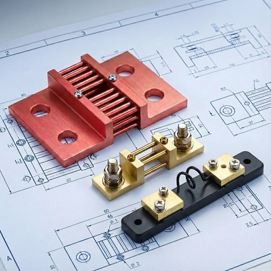
A DC current shunt is a low-resistance component installed in series with a DC circuit. Current flowing through the shunt produces a small voltage drop that a meter, controller, battery monitor, or data-acquisition system can measure. Using Ohm’s law, the system converts that voltage into a current value. Buyers should select a shunt by continuous and peak current, millivolt output, accuracy, temperature conditions, dimensions, mounting method, and terminal layout.
How Does a DC Current Shunt Work?
A shunt uses a known resistance to convert current into a measurable voltage. The basic relationship is:
V = I x R
Where:
Vis the voltage drop across the shunt.Iis the current through the shunt.Ris the shunt resistance.
Because the resistance is very low, the output is normally measured in millivolts. For example, a shunt rated at 500 A / 75 mV is designed to produce 75 mV at its rated current of 500 A. At half the rated current, an ideal linear measurement would produce half the rated millivolt output.
For a deeper explanation of the measurement relationship, see how a DC current shunt works.
Rated Current and Millivolt Output
The rated current and millivolt output must be treated as a pair. A meter configured for a 75 mV input should be matched to a shunt with the corresponding rated output unless the instrument can be reconfigured.
| Shunt marking | Meaning | Buyer must confirm |
|---|---|---|
| 100 A / 75 mV | Produces 75 mV at 100 A | Meter input and expected current range |
| 500 A / 75 mV | Produces 75 mV at 500 A | Continuous current, overload profile, and cooling |
| 1000 A / 50 mV | Produces 50 mV at 1000 A | Instrument input, cable routing, and installation space |
No output value is automatically best for every project. The correct choice depends on the measuring instrument, required signal level, power dissipation, wiring environment, and system design. The comparison in 50mV vs 75mV DC shunts explains the main selection tradeoffs.
Where Is a DC Current Shunt Used?
DC shunts are used where a system needs to measure current without placing the full current through the measuring instrument. Typical applications include:
- Battery charging and discharge monitoring
- Battery management and energy storage systems
- DC power supplies and distribution panels
- Welding equipment
- EV charging and vehicle power systems
- Industrial control and test equipment
- Switchgear and protection systems
The application determines more than the current rating. A battery system may require bidirectional measurement, a welding system may have a demanding duty cycle, and a compact power-electronics assembly may impose strict limits on dimensions and terminal placement.
How Is a DC Shunt Connected?
The current path passes through the shunt’s main current terminals. Separate sense connections measure the voltage drop across the resistance element. The measuring device is connected across the sense terminals, not placed in the high-current path.
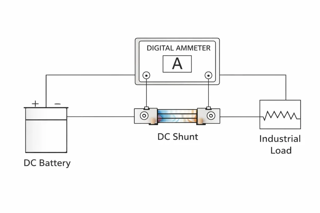
Correct wiring matters because resistance in bolts, busbars, cables, and current-carrying connections can introduce measurement error if the sense points are placed incorrectly.
Basic Wiring Checks
- Confirm the shunt’s rated current and output match the instrument configuration.
- Install the shunt in the intended current path.
- Connect the main conductors to the current terminals.
- Connect the measuring leads to the designated sense terminals.
- Maintain the required polarity when the instrument uses a polarized input.
- Keep signal wiring away from high-current conductors where practical.
- Follow the final product drawing and the measuring instrument’s instructions.
For installation details and common mistakes, use the complete DC shunt wiring diagram guide.
Which Specifications Must Buyers Confirm?
Selecting only by amperage is not enough. Electrical performance and mechanical integration must be reviewed together.
| Specification | Why it matters | Information to provide |
|---|---|---|
| Continuous current | Establishes the normal operating load | Normal current and operating duration |
| Peak or overload current | Helps evaluate short-duration stress | Peak current, pulse duration, and repetition |
| Millivolt output | Must match the meter or controller | 40, 50, 60, 75, 100 mV, or required custom output |
| Accuracy requirement | Determines allowable measurement error | Required accuracy class and operating range |
| Temperature conditions | Resistance and heat rise depend on operating conditions | Ambient temperature, enclosure, airflow, and duty cycle |
| Dimensions | Determines whether the shunt fits the assembly | Available space and dimensional limits |
| Mounting pattern | Must match the busbar, cable, or panel design | Hole size, spacing, fasteners, and orientation |
| Terminal layout | Separates the current path from the sensing path | Current terminals, sense terminals, and polarity |
| Material requirements | Affects electrical and mechanical integration | Terminal material, coating, and environmental requirements |
The DC current shunt selection guide provides a more detailed comparison of product types and application conditions.
Why Do Temperature and Power Dissipation Matter?
A shunt converts a small amount of electrical power into heat. Power dissipation follows:
P = I² x R
This means heat does not increase in direct proportion to current. When current rises, power dissipation rises with the square of the current. Selection therefore requires the real continuous current, peak profile, duty cycle, ambient temperature, enclosure conditions, and available cooling.

A rated current value should not be interpreted without the manufacturer’s stated operating conditions. A shunt installed in a ventilated test bench and the same shunt installed in a sealed cabinet may operate under different thermal conditions.
Temperature Effects to Review
- Ambient temperature around the shunt
- Heat generated by nearby busbars and components
- Continuous versus intermittent operation
- Airflow and enclosure design
- Mounting orientation and contact surfaces
- Permitted temperature rise
- Resistance stability over the required operating range
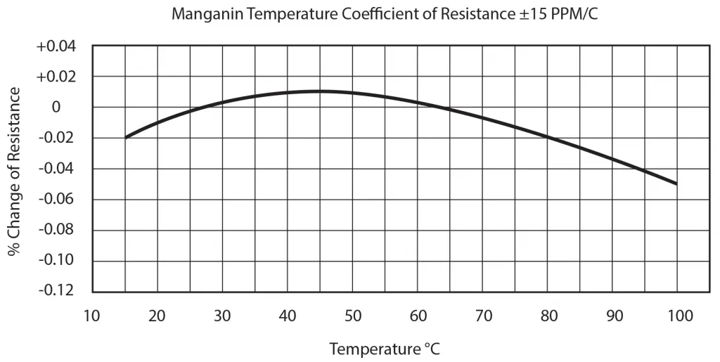
The final current capability must be confirmed for the selected model and actual installation conditions. It should not be inferred from a similar-looking shunt.
What Is Kelvin Sensing?
Many precision shunts use separate current and sense terminals. The main terminals carry the high current, while the sense terminals measure the voltage directly across the resistance element. This four-terminal arrangement is commonly called Kelvin sensing.
Separating the current and sensing connections reduces the influence of voltage drop at bolts, busbars, and current-carrying contacts. The benefit depends on correct terminal placement and wiring.
| Connection method | Current path | Measurement path | Typical concern |
|---|---|---|---|
| Two-terminal measurement | Shared terminals | Shared with current connection | Contact and conductor resistance may affect the reading |
| Four-terminal or Kelvin measurement | Main current terminals | Separate sense terminals | Sense leads must be connected to the designated points |
How Should Accuracy Be Specified?
Accuracy should be stated as a requirement tied to the application and operating conditions. A tighter nominal accuracy is not automatically the best commercial choice if the rest of the system cannot maintain that measurement performance.
The buyer should review:
- Shunt accuracy requirement
- Meter or controller accuracy
- Signal resolution
- Temperature range
- Installation and sense-lead arrangement
- Calibration or verification requirements
- Required documentation
Do not assume that an accuracy class alone defines total system accuracy. The shunt, instrument, wiring, connections, temperature conditions, and installation method all contribute to the final measurement result.
Standard or Custom DC Shunt?
A standard shunt is suitable when its current rating, output, dimensions, and terminals already match the project. A custom shunt is appropriate when the electrical target or mechanical interface differs from available models.
| Choose a standard shunt when | Consider a custom shunt when |
|---|---|
| Rated output matches the instrument | A specific resistance or current/mV output is required |
| Existing dimensions fit the assembly | Space or mounting-hole positions are fixed |
| Terminal arrangement matches the wiring | Current or sense terminals require a different layout |
| Operating conditions match the listed model | Duty cycle, peak current, or integration conditions require review |
| Standard documentation is sufficient | Project-specific drawings or verification documents are required |
LEEYD can review standard and custom DC current shunts based on the buyer’s electrical and mechanical requirements. Custom review can use a drawing or reference sample. Samples or trial orders can be followed by batch production after the specification is confirmed.
For custom projects, see the custom DC shunt buyer requirements guide and the custom DC shunt RFQ checklist.
DC Shunt or Hall Effect Current Sensor?
Both technologies measure current, but they do not solve every project in the same way.
| Decision factor | DC current shunt | Hall effect current sensor |
|---|---|---|
| Measurement principle | Measures voltage across a known resistance | Measures the magnetic field produced by current |
| Electrical isolation | Not inherent | Can provide galvanic isolation depending on sensor design |
| Power loss | Produces insertion loss and heat | Does not use a series resistance element in the same way |
| Output | Commonly a millivolt signal | Depends on sensor design and signal conditioning |
| Mechanical integration | Installed in the current path | Conductor arrangement depends on sensor type |
| Main selection question | Output, current, heat, accuracy, and mounting | Isolation, current range, bandwidth, output, and mounting |
If isolation or signal conditioning is a primary requirement, compare both technologies before fixing the architecture. The detailed DC shunt vs Hall effect current sensor guide explains the selection differences.
What Should Be Included in a DC Shunt RFQ?
An effective RFQ should contain enough information to review electrical performance and physical integration together.
Provide:
- Application and equipment type
- Continuous operating current
- Peak or overload current, duration, and repetition
- Required resistance or current/millivolt output
- Accuracy requirement
- Ambient temperature and duty cycle
- Available installation space
- Mounting-hole dimensions and terminal layout
- Current and sense terminal requirements
- Required quantity
- Drawing or reference sample, when available
- Required inspection or test documentation
Do not finalize busbars, holes, or PCB interfaces from a general catalogue image. Use the approved drawing for the selected model or custom version.
Frequently Asked Questions
Is a DC current shunt the same as a normal resistor?
A DC shunt is a low-resistance component designed for current measurement. Its resistance value, current path, sensing points, thermal behavior, and mechanical construction are selected so a measuring device can read the voltage drop and calculate current. It should not be replaced by a general-purpose resistor without engineering review.
Does a shunt reduce current?
A shunt introduces a small resistance and therefore a small voltage drop, but its purpose is to measure current rather than regulate it. The voltage drop and power dissipation must still be included in the system design.
Is 50mV or 75mV better?
Neither is universally better. The output must match the instrument and the project requirements. Signal level, power dissipation, wiring environment, and available standard models should be reviewed together.
Can a DC shunt measure current in both directions?
The shunt itself produces a voltage whose polarity changes when current direction changes. Bidirectional measurement depends on whether the connected meter or controller can interpret both polarities and whether the wiring and system design support it.
Why are there separate small terminals on some shunts?
They are sense terminals used to measure the voltage close to the resistance element. Separating sense and current connections helps reduce measurement error caused by current-terminal and connection resistance.
What information is required for a custom shunt?
Provide the resistance or current/mV target, continuous and peak current, accuracy, duty cycle, temperature conditions, dimensions, mounting holes, current terminals, sense terminals, quantity, and any required drawing or test documentation.
Request a DC Shunt Recommendation
Send the application, current profile, millivolt output, accuracy requirement, installation dimensions, terminal layout, and quantity. LEEYD can review available standard models or assess a custom design using your drawing or reference sample.