
GIS Tank-Type
Surge Arresters
Metal-enclosed, gapless metal oxide surge arresters for gas-insulated switchgear and high-voltage substation applications.
Electrical parameters, GIS interface dimensions, insulation requirements, and installation arrangements are reviewed according to the project specification and approved drawings.
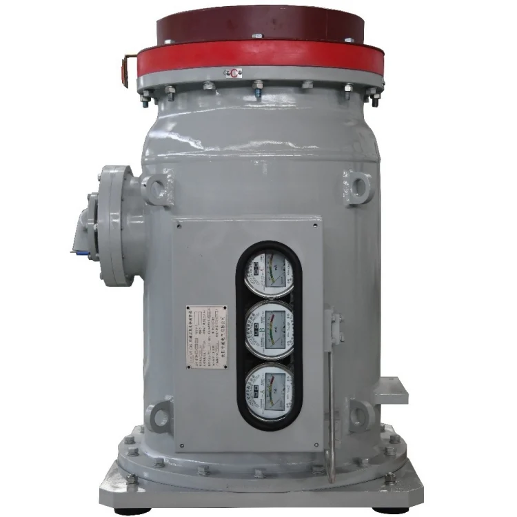
Surge Protection Integrated into GIS Systems
GIS tank-type surge arresters are designed for integration with gas-insulated switchgear, where the arrester operates within a metal-enclosed and gas-insulated system. The metal oxide varistor elements remain highly resistive under normal operating conditions and conduct surge current when the applied voltage exceeds the designed protection level.
By diverting lightning and switching surge currents toward ground, the arrester helps limit the overvoltage applied to connected GIS equipment. Its electrical characteristics, enclosure design, insulation arrangement, monitoring connection, and GIS interface must be coordinated with the system specification and installation structure.
Metal-Enclosed Integration
Designed for integration into metal-enclosed gas-insulated switchgear and related substation equipment.
Gapless Metal Oxide Protection
Metal oxide varistor elements provide nonlinear voltage-current characteristics for surge-current conduction and overvoltage limitation.
Project-Specific Interface
Electrical parameters, mechanical interfaces, insulation requirements, and monitoring connections are evaluated for each GIS project.
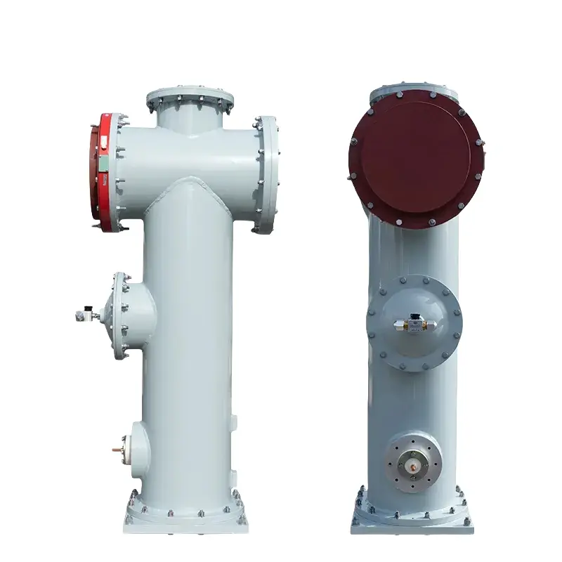
Typical GIS tank-type surge arrester configuration. Final structure is subject to project specifications and approved drawings.
Project Information Required
GIS surge arrester selection cannot be based on system voltage alone. Please provide the available electrical parameters, insulation-coordination requirements, GIS interface drawing, installation orientation, monitoring arrangement, and applicable project standard.
Main Structure & Connection Interfaces
A typical GIS tank-type surge arrester combines metal oxide varistor elements, an internal support assembly, a grounded metal enclosure, insulation interfaces, and monitoring or grounding connections. Final construction is determined by the GIS design and approved project drawings.
Metal Oxide Varistor Elements
The nonlinear resistive elements conduct surge current and help limit the overvoltage applied to connected GIS equipment. Element quantity, dimensions, and electrical characteristics are selected according to the required arrester performance.
Internal Support Assembly
The internal support and compression structure maintains the position and electrical contact of the varistor elements during handling, transportation, installation, and operation.
Voltage-Grading Components
Grading components are used to manage the electric-field and voltage distribution around the arrester assembly. Their structure and position should be coordinated with the insulation and interface design.
Grounded Metal Enclosure
The metal enclosure houses the internal arrester assembly and forms part of the metal-enclosed GIS structure. Enclosure dimensions, flange arrangement, sealing design, and gas interface are project-specific.
Insulating Interface
The insulating interface provides electrical insulation and mechanical connection between the arrester and the associated GIS equipment. Its dimensions and configuration must match the GIS manufacturer’s interface drawing.
High-Voltage, Grounding & Monitoring
Electrical connections link the arrester to the protected GIS conductor and grounding system. Where required, a monitoring connection may be provided for an arrester counter, leakage-current monitor, or other specified monitoring device.
Configuration & Project Selection Requirements
GIS surge arrester configuration depends on the electrical characteristics, insulation coordination, GIS interface, installation structure, and applicable project standards.
The information below describes a typical product concept. Final parameters and construction must be confirmed through technical review and approved drawings.
Typical Product Configuration
A project-specific configuration may include the following structural and functional elements. Availability and final design are subject to technical confirmation.
| Product type | Metal-enclosed, gapless metal oxide surge arrester |
|---|---|
| Intended integration | Gas-insulated switchgear and related GIS substation equipment |
| Protective element | Zinc oxide metal oxide varistor elements |
| Enclosure | Grounded metal enclosure with project-specific interface structure |
| Insulation arrangement | Gas-insulated configuration coordinated with the GIS system |
| High-voltage connection | Interface to the protected GIS conductor according to approved drawings |
| Grounding connection | Connection to the grounding system according to project requirements |
| Monitoring interface | Provision for an arrester counter, leakage-current monitor, or specified monitoring device where required |
| Internal support | Mechanical support and compression arrangement for the varistor assembly |
| Installation arrangement | Determined by the GIS layout, interface dimensions, and project drawing |
| Documentation | Technical specification and drawings supplied according to the confirmed project scope |
Information Required for Technical Evaluation
Please provide as much of the following information as is currently available. If some parameters have not yet been finalized, you may submit the existing GIS drawing or current arrester specification for review.
-
01
System Voltage Nominal system voltage and highest system voltage.
-
02
Arrester Electrical Ratings Required arrester rated voltage and continuous operating voltage.
-
03
Discharge Current Requirements Nominal discharge current and any required high-current or long-duration impulse capability.
-
04
Protection Level Required residual-voltage or protection-level values under the specified impulse conditions.
-
05
Insulation Coordination Lightning impulse, switching impulse, power-frequency withstand, and other applicable insulation requirements.
-
06
GIS Interface Drawing Flange dimensions, conductor interface, insulating interface, installation space, and relevant mechanical drawings.
-
07
Installation & Monitoring Installation orientation, grounding arrangement, monitoring connection, and required counter or leakage-current monitoring device.
-
08
Project Standard & Environment Applicable IEC, national, utility, or customer standards, together with the installation environment and project location.
Have an Existing GIS Drawing or Arrester Specification?
Send the available drawing, datasheet, nameplate photo, existing model reference, or technical specification. We will review the interface and electrical requirements before discussing a suitable configuration.
GIS Applications & Installation Coordination
Tank-type surge arresters are integrated into GIS equipment through project-specific electrical, insulation, and mechanical interfaces. Final application and installation must be coordinated with the GIS system design.
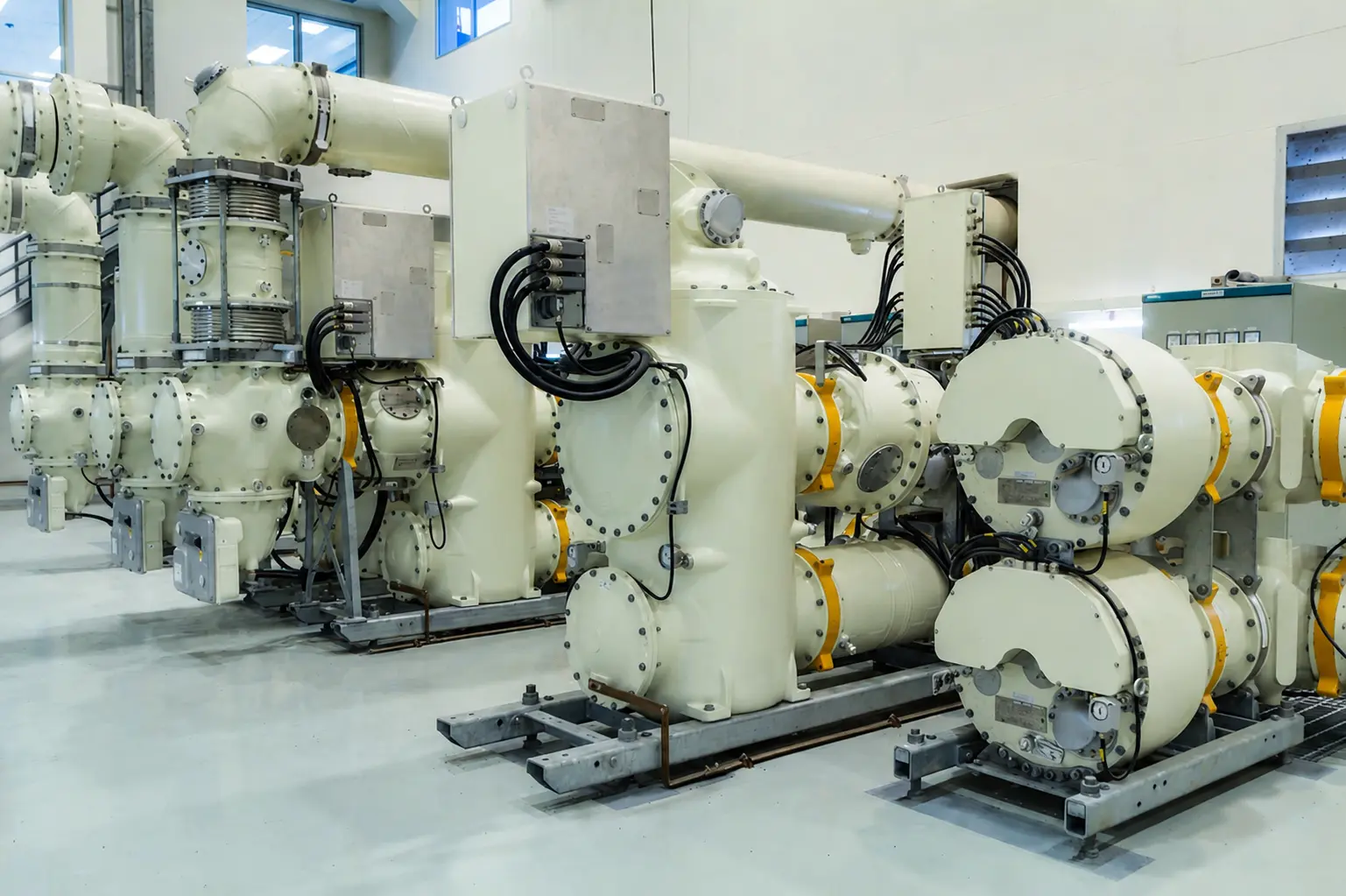
Gas-Insulated Switchgear
GIS tank-type surge arresters can be integrated into gas-insulated switchgear assemblies to help limit lightning and switching overvoltages applied to connected conductors and equipment.
The arrester configuration should be coordinated with the GIS voltage level, insulation arrangement, conductor interface, enclosure structure, gas compartment, and available installation space.
Typical GIS equipment application. Product interface and installation arrangement are project-specific.
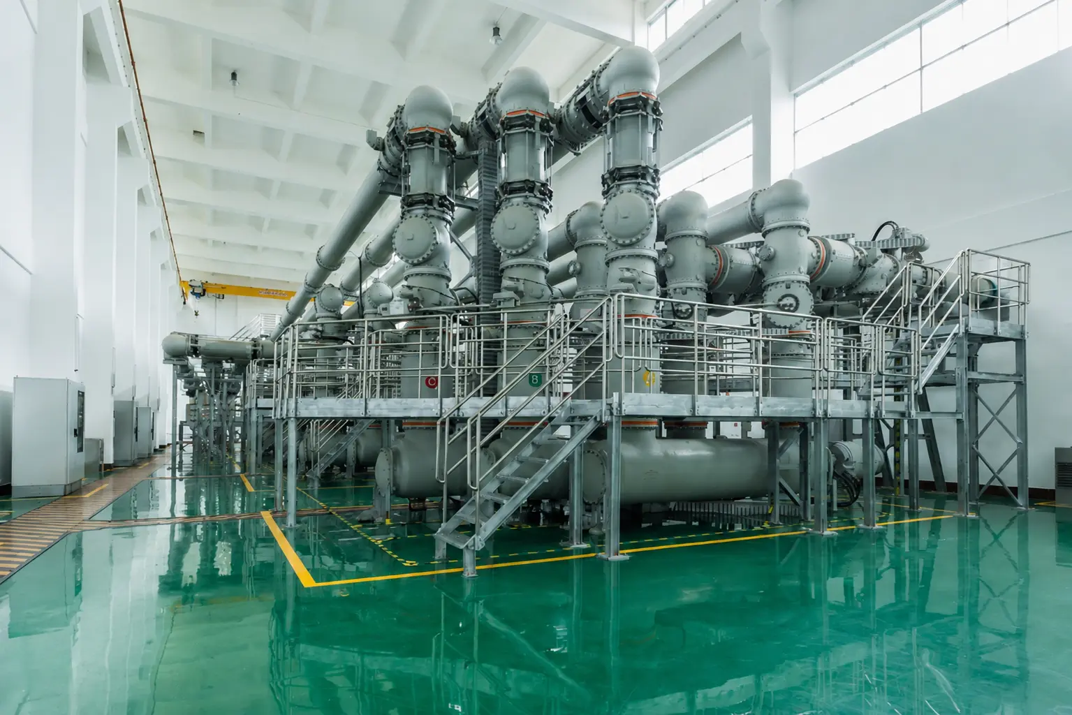
GIS High-Voltage Substations
Tank-type metal oxide surge arresters may be used within GIS-equipped substations where a compact, metal-enclosed surge-protection arrangement is required.
Selection should consider the substation insulation-coordination study, system operating conditions, required protection level, grounding arrangement, monitoring requirements, and the GIS manufacturer’s interface specification.
GIS substation application shown for reference. Final arrester selection requires project evaluation.
Installation Details to Be Confirmed
Before the arrester configuration can be finalized, the following installation and interface details should be reviewed with the GIS supplier, engineering contractor, or project owner.
01. GIS Interface Dimensions
Confirm flange dimensions, bolt pattern, conductor connection, insulating interface, installation depth, and available mechanical space.
02. Installation Orientation
Confirm whether the arrester is installed vertically, horizontally, or in another approved orientation, together with the required mechanical support.
03. Gas Compartment & Sealing
Review the gas compartment arrangement, sealing interfaces, rated filling conditions, leakage requirements, and compatibility with the GIS enclosure.
04. High-Voltage Connection
Confirm the connection between the arrester high-voltage terminal and the protected GIS conductor, including conductor position and contact arrangement.
05. Grounding & Monitoring
Confirm the grounding path and any required connection to an arrester counter, leakage-current monitor, or other project-specified monitoring equipment.
06. Installation & Testing Procedure
Installation, gas handling, electrical testing, and commissioning should follow the approved product documentation, GIS manufacturer requirements, and applicable project procedures.
Frequently Asked Questions
Common questions regarding GIS surge arrester configuration, interface evaluation, technical documentation, and project requirements.
01 | Are GIS tank-type surge arresters standard catalog products?
GIS tank-type surge arresters are generally evaluated on a project basis rather than selected only from a standard catalog. The electrical ratings, insulation requirements, enclosure, GIS interface, installation orientation, grounding connection, and monitoring arrangement must be coordinated with the specific GIS system.
Please provide the available technical specification and interface drawing before requesting a final quotation.
02 | What information is required for technical evaluation?
Please provide as much of the following information as is available:
- Nominal and highest system voltage
- Arrester rated voltage and continuous operating voltage
- Nominal discharge current
- Required residual-voltage or protection level
- Insulation-coordination requirements
- GIS interface and mechanical drawings
- Installation orientation
- Grounding and monitoring requirements
- Applicable project standards
- Required quantity and project schedule
If some parameters are not yet finalized, you may submit the existing arrester specification, nameplate photo, or GIS drawing for an initial review.
03 | Can you evaluate an existing GIS interface drawing?
Yes. Available drawings can be reviewed to understand the flange dimensions, bolt pattern, conductor connection, insulating interface, installation depth, available space, grounding path, and monitoring connection.
A drawing review does not by itself constitute final design approval. Final dimensions and construction must be confirmed through the project-specific technical agreement and approved drawings.
04 | How are the arrester electrical ratings selected?
Selection should be based on the system voltage, grounding method, temporary overvoltage conditions, insulation coordination, required protection level, nominal discharge current, and applicable project standard. System voltage alone is not sufficient for final model selection.
The required arrester rated voltage, continuous operating voltage, residual-voltage values, and impulse-current capability should be confirmed by the project engineering team.
05 | How are gas, sealing, and insulation requirements confirmed?
The insulation medium, rated gas conditions, gas-compartment arrangement, sealing interfaces, leakage requirements, and insulation levels should be defined by the GIS design and project specification.
These conditions may vary between GIS systems. They should not be assumed from a general website specification and must be confirmed before the arrester configuration is finalized.
06 | What drawings and technical documents can be discussed for the project?
The project documentation scope may include product outline drawings, interface drawings, electrical-parameter schedules, connection information, inspection requirements, and other documents agreed during technical review.
The exact document list, applicable standards, testing requirements, language, and approval process should be confirmed before order placement.
07 | Can one unit be supplied for evaluation or replacement?
Single-unit, replacement, and evaluation requirements must be reviewed according to the electrical specification, interface compatibility, documentation scope, testing requirements, and production feasibility. Please submit the existing model information and required delivery schedule for evaluation.
Discuss Your GIS Surge Arrester Requirement
Send us the available electrical parameters, GIS interface drawing, insulation requirements, installation arrangement, quantity, and applicable project standard.
We will review the submitted information before discussing the product configuration, documentation scope, technical confirmation process, and quotation.