
DC Shunt Wiring Diagram: How to Wire a Shunt Safely
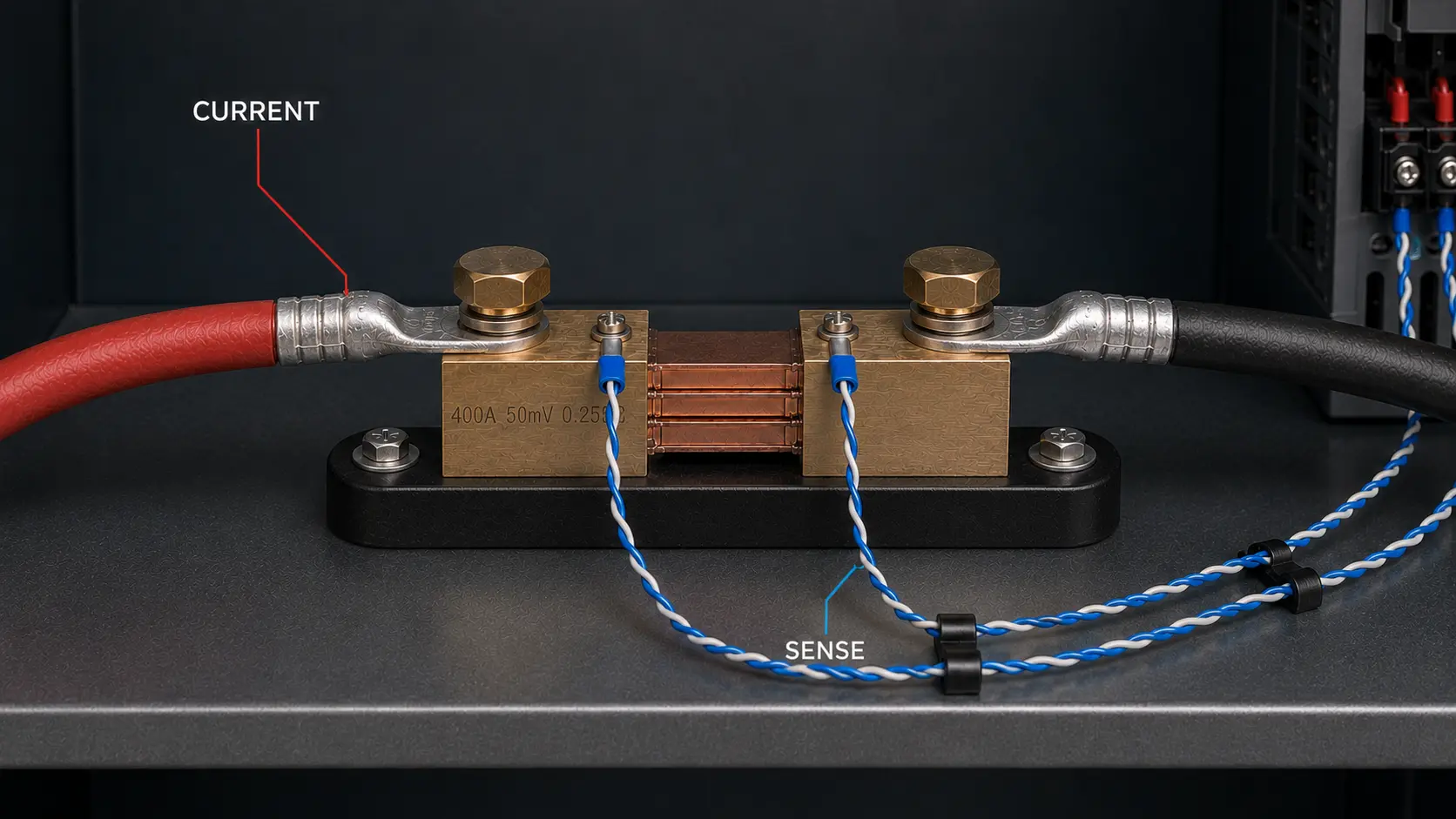
Correct DC shunt wiring separates the high-current path from the millivolt sensing circuit. Main conductors connect to the shunt’s current terminals. The meter or controller connects to the dedicated sense terminals. This setup helps the measuring device read the shunt signal without adding extra voltage drop from cables, bolts, or power connections.
This guide explains how to wire a DC current shunt. It also shows how to identify current terminals and sense terminals, match meter ratings, and avoid common wiring mistakes before energizing the circuit.
For general background on electrical shunts, you can also review this overview of an electrical shunt.
If you are still selecting the right shunt before wiring, review LEEYD’s guide on how to choose a DC current shunt.
Basic DC Shunt Wiring Diagram
Install a DC current shunt in series with the circuit you need to measure. The full load current passes through the shunt’s main current terminals. The meter reads the small millivolt signal from the shunt’s sense terminals.
In a typical external shunt connection, the wiring path is:
- DC power supply to load
- Load current path through the DC current shunt
- Main current terminals carrying the full circuit current
- Sense leads connected from the shunt to the ammeter or meter input
Do not connect the shunt as a random parallel bypass around the load. Place it in the measured current path so the circuit current also flows through the shunt.
Direct-Connected Meters vs Shunt-Connected DC Meters
Some low-current DC meters can be connected directly in series with the load. This is different from a shunt-connected DC meter. In a shunt-connected system, the load current flows through the external shunt, and the meter reads only the low millivolt signal from the shunt.
For high-current DC circuits, using an external shunt is usually more practical than routing the full current through the meter. The shunt carries the current, while the meter, display, controller, or monitoring device stays connected through small sense wires.
| Connection Type | How It Works | Typical Use |
|---|---|---|
| Direct-connected DC meter | The measured current flows through the meter | Low-current circuits |
| Shunt-connected DC meter | The measured current flows through an external shunt, and the meter reads the millivolt signal | High-current DC circuits, panels, battery systems, welding equipment, and test equipment |
Current Terminals vs Sense Terminals
Most external DC shunts have two types of terminals. The large terminals carry the main current. The smaller terminals provide the millivolt signal for the meter or measuring device.
| Terminal Type | Function | Typical Connection |
|---|---|---|
| Current terminals | Carry the measured load current | Busbars, cables, or power conductors |
| Sense terminals | Provide the millivolt measurement signal | Ammeter, meter input, controller, or data acquisition device |
Connecting the meter to the main current bolts instead of the sense terminals may introduce measurement errors. The meter may read voltage drop from the terminal joint, cable lug, or conductor connection instead of only the calibrated shunt element.
If the terminal layout does not match your panel or busbar design, review LEEYD’s standard and custom DC current shunts after confirming the wiring requirements.
How to Connect a DC Ammeter to a Shunt
Match the DC ammeter to both the rated current and the full-scale millivolt output of the shunt. Many external shunts use 50mV, 60mV, 75mV, or 100mV outputs.
For example, a 500A 75mV shunt produces 75mV at 500A. When the meter uses the same 500A / 75mV setting, the display can convert the millivolt signal into the correct current reading.
| Shunt Rating | Full-Scale Signal | Required Meter Scaling |
|---|---|---|
| 100A / 75mV | 75mV at 100A | 100A at 75mV |
| 500A / 75mV | 75mV at 500A | 500A at 75mV |
| 600A / 50mV | 50mV at 600A | 600A at 50mV |
Two shunts can have the same millivolt output but different current ratings. Matching only the voltage drop is not enough. The meter must match the complete current-to-millivolt ratio.
For a deeper explanation of voltage drop options, see LEEYD’s 75mV shunt buyer guide.
How to Check Polarity When Wiring a DC Shunt
A DC shunt produces a polarized voltage signal. If installers reverse the sense leads, the meter may show a negative value. An analog pointer may also move in the wrong direction, or a bidirectional monitoring system may report the opposite current direction.
Before powering the system, confirm:
- Current-flow direction through the shunt
- Positive and negative markings on the shunt
- Positive and negative signal inputs on the meter
- Whether the system is unidirectional or bidirectional
Do not rely only on wire color. Always verify the terminal markings and wiring diagram for the selected model.
Where Should a DC Shunt Be Installed?
The correct shunt position depends on the circuit architecture, system voltage, grounding method, meter input, and isolation requirements.
A low-side installation places the shunt in the return conductor. This is common because the sensing circuit may remain closer to the system reference potential. However, low-side installation is not always correct. It may affect grounding or create an unwanted voltage difference between the load return and system reference.
A high-side installation places the shunt in the supply conductor. This may require an isolated or differential measurement input rated for the system’s common-mode voltage.
The system designer should choose the installation point after reviewing grounding, bonding, protection, current-flow direction, and meter input isolation.
How Should Sense Leads Be Routed?
The shunt signal is usually only 50mV to 100mV at full scale, so poor sense-lead routing can introduce noise or unstable readings.
Good wiring practice includes:
- Route the two sense leads together.
- Keep sense leads away from high-current conductors where practical.
- Avoid long parallel runs near motor leads, contactor wiring, or switching cables.
- Use twisted-pair wiring when the meter or system design supports it.
- Do not use a sense wire as a shared ground or auxiliary power return.
If the shunt is far from the control system, engineers should review the cable length, noise environment, meter input, and accuracy requirement. In some systems, a local meter, signal conditioner, isolated transmitter, or differential input may give a more stable signal.
How to Install the Main Current Connections
The main current terminals carry high current, so mechanical connection quality directly affects safety and measurement stability. Contact surfaces should be clean, aligned, and suitable for the selected conductor or busbar.
Do not let large cables or busbars place unsupported mechanical stress on the calibrated shunt element. Do not use the shunt as a structural support for heavy power conductors.
During installation and commissioning, check for:
- Loose fasteners
- Uneven contact surfaces
- Unexpected heating
- Discoloration around terminals
- Cable or busbar strain
- Incorrect conductor sizing
DC Current Shunt Wiring Checklist
Before energizing the system, verify the following points.
| Check | Acceptance Point |
|---|---|
| Shunt rating | Rated current and millivolt output match the approved design |
| Meter scaling | Meter uses the same current-to-millivolt ratio as the shunt |
| Main terminals | Power conductors connect only to the designated current terminals |
| Sense terminals | Meter wires connect only to the designated sense terminals |
| Polarity | Current direction and signal polarity match the drawing |
| Shunt position | High-side or low-side location matches the system design |
| Mechanical support | Cables and busbars do not stress the shunt element |
| Signal routing | Sense leads are separated from likely interference sources |
| Initial test | Output is checked at a controlled current before full operation |
How to Verify the Shunt Wiring
Start initial testing under controlled conditions and follow the equipment’s electrical safety procedure. Measure the voltage directly across the dedicated sense terminals with an appropriate DC millivolt instrument.
Compare the measured signal with the expected value calculated from the shunt ratio. For example, a 400A / 75mV shunt should ideally produce:
- 18.75mV at 100A
- 37.5mV at 200A
- 75mV at 400A
If the direct millivolt measurement is correct but the displayed current is wrong, check the meter scaling, polarity, signal wiring, and input configuration. If the millivolt signal is unstable, inspect the power connections, sense-lead routing, load stability, and possible electrical interference before assuming the shunt has failed.
Common DC Shunt Wiring Mistakes
- Connecting the meter to the main current terminals instead of the sense terminals.
- Using a 75mV meter with a 50mV shunt without reprogramming the meter.
- Reversing the sense lead polarity.
- Installing the shunt only where it is convenient instead of where the circuit design requires it.
- Routing sense leads beside high-current or switching conductors for long distances.
- Allowing heavy cables or busbars to stress the shunt body.
- Ignoring abnormal heat at current terminals during commissioning.
LEEYD DC Shunts for Wiring and Installation Projects
LEEYD manufactures DC current shunts and custom DC shunt resistors with different current ratings, millivolt outputs, terminal layouts, and mounting structures.
For this wiring page, the most useful RFQ details are the rated current, voltage drop, meter input, terminal arrangement, installation space, and any available wiring drawing or sample. For broader model selection, use the DC current shunt selection guide.
Frequently Asked Questions
Can the meter connect to the large shunt terminals?
The meter should normally connect to the dedicated sense terminals. If you connect it to the main current terminals, the meter may also read voltage drop from the bolted power connections. This can reduce measurement accuracy or cause unstable readings.
Can a 75mV meter work with a 50mV shunt?
Only if the meter can be programmed for the exact 50mV shunt ratio. A fixed 75mV meter will display the wrong current when connected to a 50mV shunt. Both the rated current and the full-scale millivolt output must match.
Must a DC shunt always be installed in the negative conductor?
No. A return-side installation is common, but it is not a universal rule. The correct position depends on grounding, isolation, common-mode voltage, protection design, and the connected instrument.
Why does the meter show a negative current?
The sense lead polarity or defined current direction may be reversed. Check the shunt terminal markings, current-flow direction, and meter input polarity. In a bidirectional system, a negative value can also represent reverse current.
Can the sense leads be extended?
They can be extended when the meter input and system design permit it. Long leads may increase exposure to interference, ground-potential differences, or lead-resistance effects. Check the meter specification and consider twisted-pair wiring or signal conditioning when required.
Review the Shunt Rating and Wiring Requirements
Before approving a DC shunt installation, confirm the rated current, millivolt output, accuracy requirement, meter input, terminal arrangement, installation space, and grounding design.
For product selection or custom configuration, review LEEYD’s standard and custom DC current shunts or send your wiring drawing, expected current range, meter model, and installation conditions for evaluation.