
Welding Shunt Selection Guide for DC Welding Machines
A welding shunt is used to measure high welding current by converting the current into a small millivolt signal for a meter, controller, or monitoring system. In inverter welders, IGBT welding machines, resistance welding equipment, and industrial welding power supplies, the shunt must match the current profile, controller input, heat conditions, and mechanical layout.
This page is a welding shunt selection guide. It explains how to choose a DC current shunt for welding equipment by current rating, mV output, accuracy, duty cycle, terminal structure, mounting space, and sample validation. If you are diagnosing an unstable current reading or abnormal heat on an existing machine, use the separate welding machine shunt troubleshooting guide.
Why Welding Machines Need an Application-Specific DC Shunt
Welding current is not always a steady DC load. Depending on the machine and process, the current may include pulses, short high-current peaks, repeated duty cycles, and fast control changes. A standard DC shunt may work only when its electrical rating and mechanical structure fit the actual welding application.
For welding equipment, the shunt should be reviewed as part of the current feedback path. The wrong shunt ratio can create incorrect current display. Poor terminal contact can add heat. Bad sense wiring can make feedback unstable. Limited mounting space can force a custom structure even when the current rating looks correct.
If you need the measurement principle before selecting a model, read how a DC current shunt works.
Step 1: Define the Welding Current Profile
Start with the real welding current profile, not only the maximum current printed on the machine nameplate. The shunt must handle the current that flows through the measurement path under normal work, peak output, repeated starts, and overload conditions.
| Current Detail | What to Confirm | Why It Matters |
|---|---|---|
| Normal working current | Typical current during regular welding | Helps select a practical operating range |
| Maximum output current | Highest rated current of the machine | Prevents undersizing |
| Peak or pulse current | Peak value and duration | Affects thermal and overload review |
| Duty cycle | Current level, welding time, and rest time | Determines heat buildup |
| Control response | How fast feedback must respond | Affects signal routing and filtering decisions |
Step 2: Match the mV Output to the Controller
The controller, meter, or current display must match the full-scale millivolt output of the shunt. Common DC shunt outputs include 50mV, 60mV, 75mV, 100mV, and custom values. A 500A/75mV shunt should be used with a meter or controller scaled for 500A at 75mV.
Do not choose the welding shunt by current rating alone. The current rating and mV output must be treated as one ratio. If the controller input is fixed, the welding shunt output should follow that input. If the controller can be programmed, confirm the accepted input range and scaling method before ordering.
For a deeper explanation of 75mV output and meter matching, see the 75mV shunt guide.
Step 3: Set Accuracy for the Welding Function
The required accuracy depends on how the welding machine uses the current signal. A basic panel display may not need the same precision as closed-loop current control, production monitoring, or test equipment. Define the accuracy requirement before comparing models.
| Measurement Function | Accuracy Concern | Selection Note |
|---|---|---|
| Panel current display | Readable current indication | Standard accuracy may be enough |
| Current feedback control | Stable and repeatable signal | Review shunt accuracy and wiring quality |
| Weld quality monitoring | Consistent current data across cycles | Check thermal stability and controller input |
| Testing or calibration | Higher measurement confidence | Define tolerance and validation method clearly |
Step 4: Evaluate Duty Cycle, Heat, and Overload
A DC shunt produces heat because welding current flows through a low resistance element. Even a small voltage drop can create meaningful heat at high current. A 1000A/75mV shunt, for example, dissipates about 75W at full current.
For welding machines, check the duty cycle and cooling conditions carefully. Enclosed space, poor airflow, repeated peak current, and heavy cable stress can all affect shunt temperature and long-term stability.
Step 5: Confirm Structure, Terminals, and Mounting Space
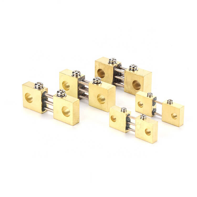
Electrical rating is only part of the selection. The welding shunt must physically fit the machine. Confirm the available space, mounting holes, busbar direction, screw size, terminal material, and distance between current and sense terminals.
Current terminals carry the welding current. Sense terminals provide the millivolt signal to the meter or controller. Mixing these connections can cause measurement errors. For wiring details, read the DC shunt wiring diagram guide.
Step 6: Decide Between Standard and Custom Welding Shunts
A standard model is suitable when the current rating, mV output, accuracy, and mounting dimensions match the welding machine. A custom welding shunt is more appropriate when the equipment has a special busbar layout, limited installation space, non-standard terminal material, or OEM-specific mechanical requirements.
| Requirement | Standard Shunt | Custom Shunt |
|---|---|---|
| Common current and mV rating | Usually suitable | Optional |
| Special busbar shape | May not fit | Recommended |
| Limited cabinet space | Check drawing first | Often useful |
| OEM welding machine integration | Possible if dimensions match | Often preferred |
| Replacement for existing sample | Possible if model matches | Recommended when structure differs |
To compare available product types, review the LEEYD DC current shunt product series.
Welding Shunt Selection Checklist
| Item | Information to Provide |
|---|---|
| Welding machine type | Inverter welder, IGBT welder, resistance welding equipment, or other system |
| Current rating | Normal, maximum, peak, and duty-cycle current |
| mV output | 50mV, 60mV, 75mV, 100mV, or custom |
| Controller input | Full-scale input, polarity, scaling, and response requirements |
| Accuracy | Required class or tolerance |
| Thermal condition | Ambient temperature, airflow, enclosure, and overload condition |
| Mechanical layout | Drawing, hole position, dimensions, terminal material, and busbar layout |
| Validation | Sample test current, output check, and acceptance method |
How This Selection Page Differs From Troubleshooting
This page helps select a DC shunt before purchase or machine integration. If the welding machine already has a shunt installed and the current reading is unstable, inaccurate, or overheating, use the welding machine shunt troubleshooting guide instead.
Frequently Asked Questions
What is a welding machine DC shunt?
It is a low-resistance measuring component installed in the welding-current path. It creates a millivolt signal that a meter or controller uses to display or control welding current.
Is 75mV always the best output for a welding shunt?
No. 75mV is common, but the correct output depends on the meter or controller input. Some systems require 50mV, 60mV, 100mV, or a custom value.
Can one shunt work for different welding machines?
Only if the current rating, mV output, accuracy, terminal layout, mounting dimensions, and thermal conditions match each machine.
When is a custom welding shunt needed?
A custom shunt is useful when the welding machine requires a special busbar shape, mounting hole position, terminal material, compact structure, or non-standard current and mV rating.
What should I send for a welding shunt quotation?
Send the current rating, mV output, controller input, accuracy requirement, duty cycle, drawing, terminal layout, mounting space, and expected quantity.
Need a DC current shunt for welding equipment? Send your welding current profile, required millivolt output, controller input, and installation drawing to LEEYD for standard model selection or custom design support.