
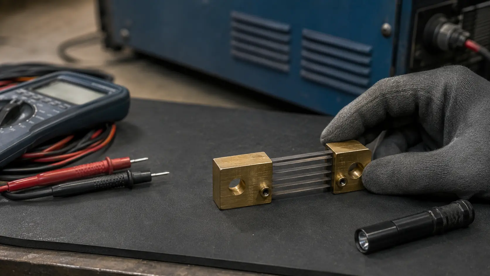
Shunt Welding Machine Troubleshooting: 5 DC Current Checks
A shunt welding machine setup uses a calibrated shunt to help the control system measure welding current through a small millivolt signal. When the welding machine shunt, meter scaling, wiring, or terminals are wrong, the machine may show unstable current feedback, incorrect readings, abnormal heat, or inconsistent weld quality.
This page is a troubleshooting guide for a shunt welding machine current-measurement path. It focuses on diagnosis: how to check the shunt ratio, current terminals, sense wiring, millivolt signal, heating, and EMI. For model selection, use the separate welding machine DC shunt selection guide.
What Does a Welding Machine Shunt Do?
In a DC welding machine, the shunt is installed in the welding-current path. The main welding current passes through the welding machine shunt body, while the meter or control board reads a low-voltage signal from the sense terminals. This signal is used for current display, feedback control, monitoring, or quality checks.
The measurement principle is the same as other DC current shunts: current creates a proportional millivolt output across a calibrated low-resistance element. If you need the basic principle, see how a DC current shunt works.
Start With the Symptom, Not the Shunt
Do not replace the welding shunt immediately when current feedback looks wrong. First identify the symptom and check whether the problem comes from the shunt, the wiring, the meter setting, the control board, or the power connection.
| Symptom | Possible Cause | First Check |
|---|---|---|
| Displayed current is too high or too low | Wrong meter ratio or wrong shunt mV rating | Compare meter setting with shunt label |
| Current reading jumps during welding | Loose sense lead, EMI, or unstable connection | Inspect sense wiring and terminal tightness |
| Shunt terminals overheat | Poor contact, undersized conductor, or overload | Check main current terminals and busbar contact |
| No current reading | Open sense wire, reversed connection, or failed input | Measure mV directly at shunt sense terminals |
| Reading is correct at low current but wrong at high current | Thermal drift, connection heating, or current-path problem | Check heating and repeat test at multiple current levels |
Check 1: Confirm the Welding Machine Shunt and Meter Ratings
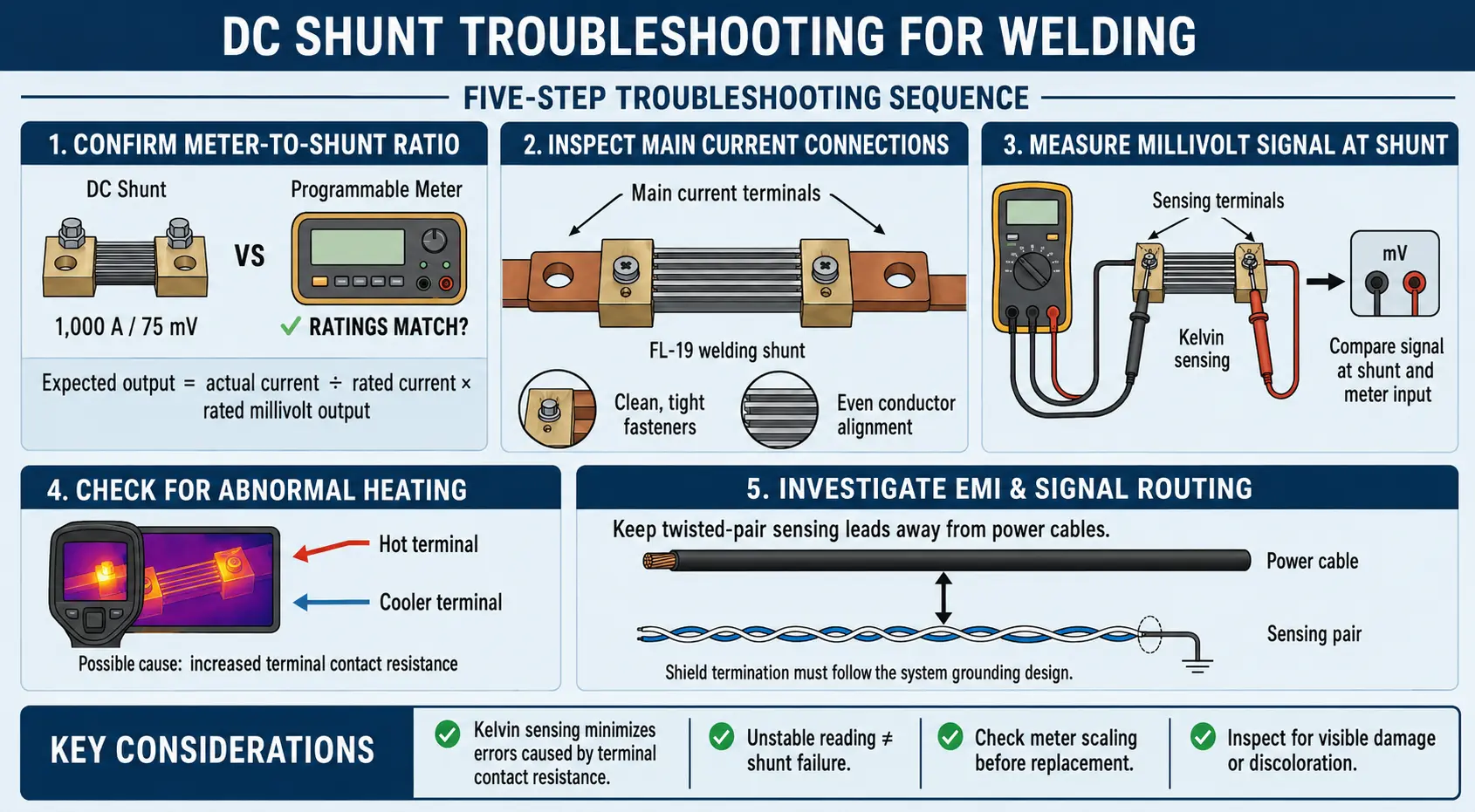
The welding machine shunt and meter must use the same current-to-millivolt ratio. A 500A/75mV shunt should be read by a meter or controller configured for 500A at 75mV. If the meter is set for 500A/50mV or 1000A/75mV, the displayed welding current will be wrong.
Check the shunt marking, drawing, meter input specification, and controller scaling parameter. For details on 75mV matching, see the 75mV shunt guide.
| Shunt Rating | Expected Full-Scale Output | Meter Must Be Set To |
|---|---|---|
| 300A / 75mV | 75mV at 300A | 300A / 75mV |
| 500A / 75mV | 75mV at 500A | 500A / 75mV |
| 600A / 50mV | 50mV at 600A | 600A / 50mV |
Check 2: Inspect Current Terminals and Sense Terminals
A welding shunt normally has main current terminals and smaller sense terminals. The main welding current must pass through the current terminals. The meter or controller should read the signal from the dedicated sense terminals.
If the sense wires are connected to the main bolts, busbar, or cable lug instead of the sense terminals, the measurement may include extra voltage drop from the connection. This can make the current reading unstable, especially under high welding current.
For detailed installation guidance, use the DC shunt wiring diagram guide.
Check 3: Measure the Millivolt Signal at the Shunt
When possible, measure the DC millivolt signal directly at the shunt sense terminals during a controlled test. Compare the value with the expected output from the shunt ratio. This helps separate a real shunt signal problem from a meter, controller, or cable problem.
For example, a 500A/75mV welding shunt should produce about 37.5mV at 250A and 75mV at 500A. If the signal at the shunt is correct but the display is wrong, check the meter scaling and input wiring. If the signal at the shunt is already wrong, inspect the current path, terminal contact, and shunt condition.
Check 4: Look for Abnormal Heating
Welding current is often high and may include repeated peaks. Some heat is normal, but abnormal heating around the terminals or shunt body can indicate poor contact, loose fasteners, overload, mechanical stress, or unsuitable current rating.
After following the equipment safety procedure, inspect the connection surfaces, fasteners, cable lugs, busbars, and signs of discoloration. Do not use the shunt body as mechanical support for heavy cables or unsupported busbars.
Check 5: Review EMI and Sense Lead Routing
Welding machines can create electrical noise from switching devices, contactors, long cables, and arc conditions. Because a shunt signal is only tens of millivolts, poor sense-lead routing can cause unstable readings.
- Route the sense leads together.
- Keep signal wires away from high-current and switching conductors where practical.
- Avoid long parallel runs beside welding cables.
- Use twisted-pair or shielded wiring when the control design requires it.
- Do not use a sense lead as a shared power return or auxiliary ground.
If the machine still shows unstable current feedback, check whether the controller input needs filtering, isolation, or a different signal-conditioning method. Filtering should be reviewed carefully because too much filtering may slow the current-feedback response.
When Should a Welding Machine Shunt Be Replaced?
Replace or redesign the welding machine shunt when inspection shows physical damage, loose or overheated terminals, unstable millivolt output, incorrect resistance, mechanical deformation, or a current rating that no longer matches the welding process.
If the welding machine shunt ratio, wiring, and millivolt output are correct, the problem may come from the meter, controller input, welding cable layout, grounding, or power circuit rather than the shunt itself.
Welding Shunt Troubleshooting Checklist
| Check | What to Verify |
|---|---|
| Shunt label | Rated current and mV output match the approved design |
| Meter setting | Controller or ammeter uses the same current-to-mV ratio |
| Main current path | Welding current passes through the correct current terminals |
| Sense wiring | Signal wires connect to the dedicated sense terminals |
| Polarity | Positive and negative sense connections match the meter input |
| mV output | Signal measured at the shunt matches the expected value |
| Heat | No abnormal temperature rise, discoloration, or loose connection |
| EMI | Sense leads are routed away from major interference sources |
LEEYD DC Shunts for Welding Equipment
LEEYD manufactures standard and custom DC current shunts for welding equipment, battery systems, EV and energy storage systems, switchgear, industrial power systems, and test equipment.
For a welding-machine shunt request, send the rated current, voltage drop, meter or controller input, duty cycle, available space, terminal layout, and any existing drawing or sample. If you need to choose a model rather than troubleshoot an existing one, start with the welding machine DC shunt selection guide.
Frequently Asked Questions
What does a shunt do in a welding machine?
It converts welding current into a small millivolt signal that a meter or controller can read for current display, feedback, or monitoring.
Why is the welding current display unstable?
Common causes include loose sense wiring, incorrect meter scaling, poor current-terminal contact, EMI, or an unstable millivolt signal from the shunt.
Can a welding machine use a 75mV shunt?
Yes, if the meter or controller is designed or configured for the same current rating and 75mV full-scale output.
Should the meter connect to the main shunt bolts?
The meter should normally connect to the dedicated sense terminals. Connecting to the main bolts may add contact voltage drop and reduce measurement accuracy.
What information should I send for a replacement welding shunt?
Send the current rating, mV output, accuracy requirement, installation dimensions, terminal layout, meter input, duty cycle, and photos or drawings of the existing shunt.
Need help checking a welding machine shunt? Share the shunt label, meter setting, wiring drawing, and symptom description with LEEYD so the current measurement path can be reviewed.