
75mV Shunt Guide: Output, Meter Matching, and 50mV Comparison
A 75mV shunt is a DC current shunt that produces 75 millivolts at its rated current. For example, a 100A/75mV shunt outputs 75mV when 100A flows through the current terminals. A 500A/75mV shunt also outputs 75mV at full load, but its resistance and heat dissipation are different.
For buyers, the key point is simple: 75mV is not the current rating. It is the full-scale voltage signal used by the ammeter, meter, PLC, battery monitor, or control system. Before ordering a DC current shunt, confirm the current rating, voltage drop, accuracy, mounting layout, and the instrument input together.
This guide stays focused on the 75mV signal itself: what it means, how to calculate output, how to match the meter input, and when to compare 50mV vs 75mV. For complete product selection, use the separate DC shunt selection guide linked below.
What Does 75mV Mean on a DC Shunt?
On a DC shunt, 75mV means the shunt is designed to create a 75 millivolt signal at rated current. The measuring instrument reads this small voltage and displays the corresponding current value.
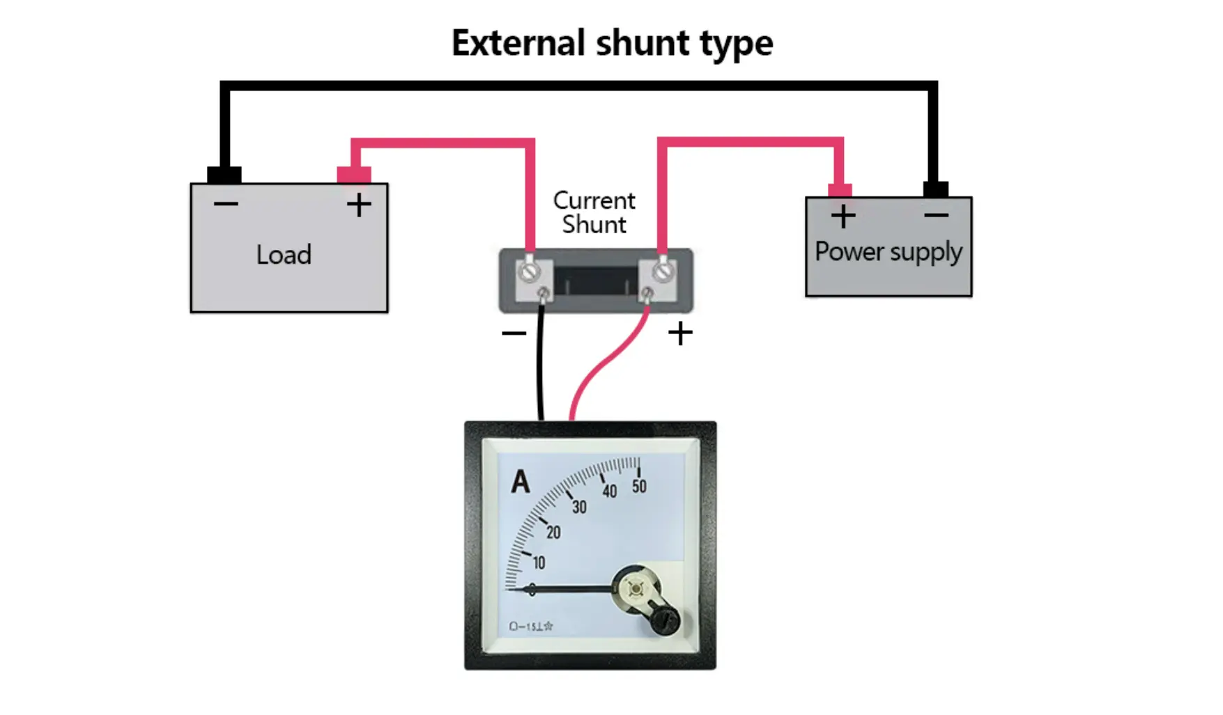
A shunt is a low-resistance path used for current measurement. In practical systems, the main current passes through the heavy current terminals, while the meter reads the millivolt signal from the sense terminals. For a general technical definition, see this overview of an electrical shunt.
The relationship is linear when the shunt and meter are matched correctly:
| Output voltage | Measured current / Rated current x 75mV |
| Measured current | Output voltage / 75mV x Rated current |
If the meter expects a 75mV input, the shunt must normally be a 75mV shunt with the matching current range. If the meter expects 50mV or 100mV, using a 75mV shunt can cause incorrect display scaling unless the instrument is configurable.
Example: 100A / 75mV Shunt Output
For a 100A/75mV shunt, 100A equals 75mV. At lower current, the millivolt output drops in the same proportion.
| Current Through Shunt | Expected Output | Meter Reading if Scaled for 100A/75mV |
|---|---|---|
| 25A | 18.75mV | 25A |
| 50A | 37.5mV | 50A |
| 75A | 56.25mV | 75A |
| 100A | 75mV | 100A |
This is why the current rating and the millivolt output must be specified as a pair. A 100A/75mV shunt and a 500A/75mV shunt both produce 75mV at full scale, but they are not interchangeable in a high-current circuit.
Resistance and Power of Common 75mV Shunts
The shunt resistance is calculated from Ohm’s law. As current rating increases, resistance decreases, but power dissipation at full current increases. This affects temperature rise, mounting space, and material selection.
| Shunt Rating | Nominal Resistance | Power at Rated Current |
|---|---|---|
| 100A/75mV | 750 micro-ohms | 7.5W |
| 500A/75mV | 150 micro-ohms | 37.5W |
| 1,000A/75mV | 75 micro-ohms | 75W |
For continuous current, high ambient temperature, enclosed panels, or limited airflow, do not choose the shunt only by nominal current. Thermal conditions can decide whether a standard model is suitable or whether a custom structure is needed.
50mV vs 75mV Shunt: Which One Should You Choose?
Both 50mV and 75mV shunts are common in DC current measurement. The right choice usually depends on the meter input and the system design, not on one value being universally better.
| Item | 50mV Shunt | 75mV Shunt |
|---|---|---|
| Meter compatibility | Use when the instrument is scaled for 50mV | Use when the instrument is scaled for 75mV |
| Signal level | Lower millivolt signal at full scale | Higher millivolt signal at full scale |
| Power dissipation at same current | Lower than 75mV | Higher than 50mV |
| Typical decision factor | Lower voltage drop or specified meter input | Common ammeter and monitoring input requirement |
If the existing meter is fixed at 75mV, choose a 75mV shunt. If you are designing a new system, compare the measurement input, allowable voltage drop, heat, installation space, and expected current profile before finalizing the value.
5 Details That Affect a 75mV Shunt Reading
For this page, the key question is whether the 75mV signal will be read correctly. Confirm these details before replacing a shunt or matching it with an ammeter.
1. Rated Current
Confirm the complete ratio, such as 50A/75mV, 100A/75mV, 500A/75mV, or 1,000A/75mV. The 75mV value only defines the full-scale output; the current rating defines the ampere range.
2. Meter Input
Confirm that the ammeter, controller, or monitoring device is scaled for 75mV. A fixed 50mV or 100mV meter will not display the correct current with a 75mV shunt unless it can be reconfigured.
3. Accuracy Class
Accuracy requirements should be stated clearly, especially for test equipment, battery monitoring, energy systems, and industrial control panels. Include the required tolerance or accuracy class if your drawing specifies one.
4. Duty Cycle and Heat
Heat matters because a shunt carries the main load current. Share the ambient temperature, enclosure condition, airflow, duty cycle, and any nearby heat source. These details help confirm whether the selected model can operate reliably.
5. Terminal and Wiring Layout
Current terminals and sense terminals serve different purposes. Heavy current should pass through the main terminals, while the meter signal should be taken from the designated sense points. If you need wiring guidance, see our DC shunt wiring diagram guide.
Can a 75mV Ammeter Work With Any Shunt?
No. A 75mV ammeter should be matched with a shunt that has the same full-scale millivolt output and the correct current range. For example, a 100A/75mV meter should normally be paired with a 100A/75mV shunt. If the shunt current rating is different, the meter reading will not match the real current unless the instrument is set for that ratio.
Polarity also matters. Reversed sense wiring may cause a negative reading, no reading, or unstable display depending on the instrument. Always confirm the meter manual and the shunt terminal markings before energizing the system.
When to Use the Selection Guide Instead
This page explains the 75mV output. If you also need to compare applications, current range, mounting style, terminal material, or custom busbar layout, use the broader DC current shunt selection guide.
To compare available models and custom options, view the LEEYD DC shunt product series.
FAQ About 75mV Shunts
What is a 75mV shunt?
A 75mV shunt is a low-resistance DC current measuring component that outputs 75 millivolts at its rated current. The meter reads this millivolt signal and displays the current value.
Is 75mV the same as 0.075V?
Yes. 75mV equals 0.075V. In shunt selection, it is usually written as 75mV because the signal is small and used for current measurement.
Can I replace a 50mV shunt with a 75mV shunt?
Only if the meter or control system can be configured for the new shunt output. If a meter is fixed for 50mV, a 75mV shunt can create an incorrect reading.
How do I calculate current from a 75mV shunt?
Divide the measured millivolt output by 75mV, then multiply by the shunt rated current. For a 100A/75mV shunt, 37.5mV represents 50A.
What should I send when ordering a custom 75mV shunt?
Send the rated current, voltage drop, accuracy requirement, drawing or dimensions, mounting holes, terminal material, application, duty cycle, and expected order quantity.
Need help selecting a 75mV DC shunt? Share your current rating, meter input, mounting space, and application requirements with LEEYD for model selection or custom design support.