

DC current shunt applications have different electrical, thermal, mechanical, and validation requirements. A shunt used in a welding machine must handle pulsed current and electrical noise, while one used in a battery system may face long continuous loads. Switchgear emphasizes busbar integration and service access. Test systems place greater weight on accuracy and documented test conditions. The application therefore determines more than the current rating; it defines how the shunt should be specified and verified.
How Application Conditions Change DC Shunt Requirements
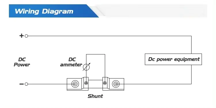
A DC current shunt is a calibrated low-resistance component installed in the main current path. The measured current passes through its current terminals. A meter or control system reads the small voltage drop across the separate potential terminals.
Conventional external shunts are used for system-level current measurement in industrial equipment. They are not interchangeable solely because they share the same current rating and millivolt output. The application changes the conditions under which those ratings must perform.
Current Profile and Duty Cycle
The current profile describes how current changes over time. It should distinguish normal operating current, maximum continuous current, short peaks, overload duration, pulse frequency, and recovery time.
A 500 A continuous load creates a different thermal condition from a 500 A pulse lasting a fraction of the operating cycle. Welding systems, chargers, rectifiers, battery equipment, and test benches can all reach similar current levels while imposing different loads on the shunt.
Signal and Measurement Function
The required millivolt output must match the connected meter, controller, or data-acquisition input.
The function of that signal also matters. A general display, control loop, protection circuit, energy-monitoring system, and calibration bench may have different accuracy and stability requirements.
Thermal and Installation Environment
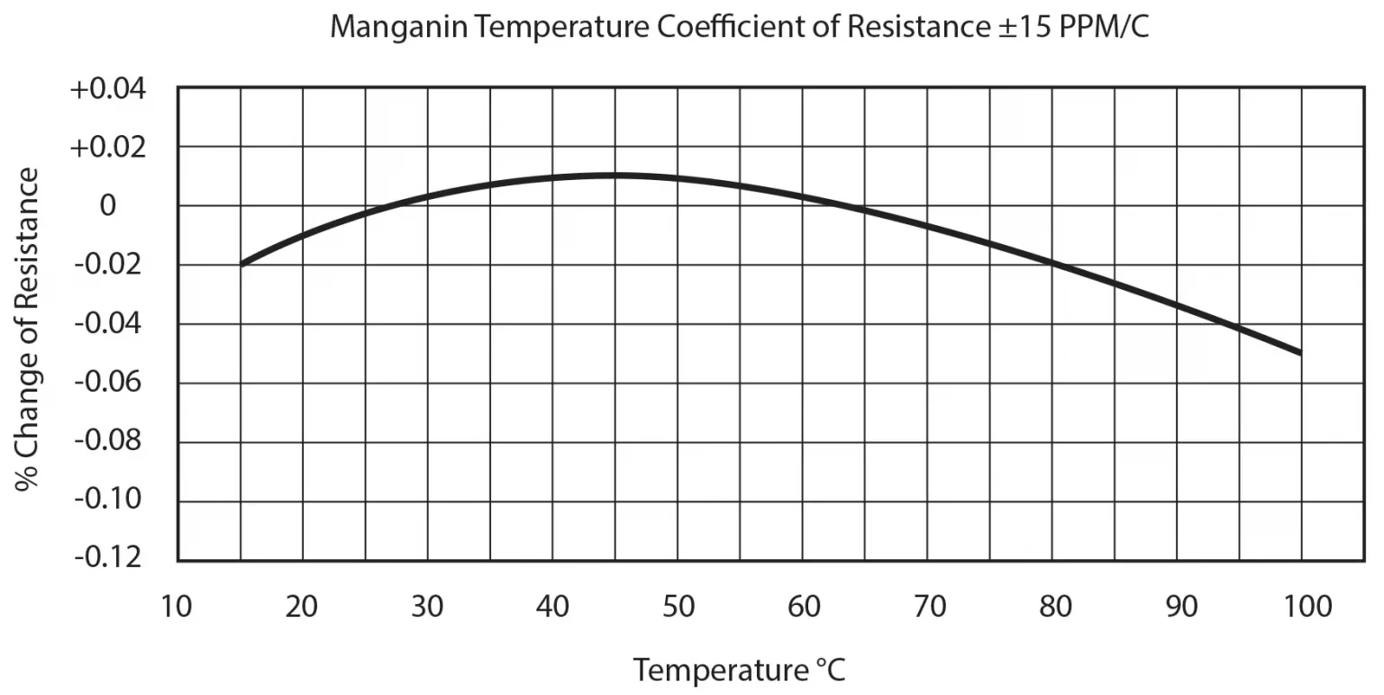
Ambient temperature, ventilation, installation orientation, nearby heat sources, contact quality, and available cooling space can affect temperature rise and measurement stability.
There is no single derating percentage that applies to every shunt and every installation.
Mechanical Integration
The equipment layout determines the acceptable length, width, height, terminal arrangement, mounting-hole pattern, busbar connection, cable access, and mechanical support.
Two electrically similar shunts may require different structures because their installation environments differ.
Validation Method
The application also defines what must be checked before approval.
Depending on the project, validation may include rated voltage drop, output stability, dimensions, terminal fit, mounting alignment, temperature behavior, markings, or test records.
| Application | Dominant Operating Condition | Main Engineering Concern | Important Validation Point |
|---|---|---|---|
| Industrial power and conversion equipment | Continuous or changing high current | Heat, signal compatibility, and cabinet integration | Output under the agreed current and operating conditions |
| Welding equipment | Pulsed current and electrical noise | Duty cycle, peak current, and signal stability | Output behavior during the actual welding cycle |
| DC switchgear and distribution | High current through busbars | Mechanical interface, clearances, and service access | Busbar alignment, terminal fit, and signal routing |
| Battery and energy storage | Long continuous and bidirectional current | Thermal stability and charge/discharge measurement | Positive and negative current scaling in the complete system |
| Test and calibration systems | Controlled measurement conditions | Accuracy, stability, and traceable acceptance conditions | Defined test current, temperature, equipment, and records |
For the general parameter-selection process, use the DC current shunt selection guide. The sections below focus on how each application changes those requirements.
Industrial Power and Power Conversion Equipment
Industrial DC power supplies, rectifiers, chargers, UPS systems, inverters, and DC/DC equipment use shunts for current indication, control, protection support, or system monitoring.
These applications often combine sustained current with changing load levels inside an enclosure.
Review Continuous Loading and Internal Heat
The first question is how long the equipment operates near its normal or maximum current. A rectifier serving a continuous industrial process imposes a different thermal load from equipment that runs intermittently.
The RFQ or design review should identify:
- Normal operating current.
- Maximum continuous current and duration.
- Short overload or startup conditions.
- Internal ambient temperature.
- Airflow and nearby heat-producing components.
- Available clearance around the shunt.
Rated power capability varies with operating conditions. The shunt should be reviewed inside the equipment’s thermal environment, not only at room temperature outside the enclosure.
Match the Signal to the Control Architecture
Industrial equipment may connect the shunt to an analog panel meter, controller, signal conditioner, or data-acquisition input.
The rated current and millivolt output form a matched pair. A 1,000 A/75 mV shunt is not a direct electrical replacement for a 1,000 A/50 mV shunt unless the receiving system is configured for the different input.
Signal polarity, cable routing, grounding, shielding, and controller scaling should be checked as one measurement chain.
A suitable shunt cannot correct an incorrectly scaled instrument or poor signal routing.
Confirm the Enclosure and Connection Interface
Industrial power equipment may require a base-mounted, flat, compact, or customized structure.
Engineers should compare the shunt drawing with the cabinet layout, conductors, busbars, airflow path, and maintenance access.
LEEYD lists standard, flat-type, compact, high-current, and customized structures for different industrial layouts. Final suitability still depends on the selected model, current rating, installation method, and operating conditions.
Welding Equipment
Welding machines create one of the more demanding DC shunt applications.
The current can be pulsed, the duty cycle varies by process, and the electrical environment can be noisy. A welding shunt should therefore be evaluated against the real welding cycle rather than only the machine’s maximum current label.
Define the Welding Current Profile
Provide the normal welding range, maximum output current, pulse duration, duty cycle, pulse frequency when applicable, and recovery time.
Also identify whether the reading is used for operator display, process control, monitoring, or another function.
Oversizing the current rating without checking the normal signal level can reduce measurement resolution. At the same time, selecting only for the average current may ignore short peaks and their thermal effect.
Account for Electrical Noise
The shunt produces a low-level millivolt signal inside equipment carrying high current.
The sensing wires should connect to the designated potential terminals. Their routing should account for high-current conductors and switching components.
This application article does not replace a complete wiring guide. The main application requirement is that the shunt structure, signal terminals, instrument input, and wiring arrangement must be evaluated together under the actual welding conditions.
Verify the Structure in the Welding Assembly
Welding equipment may impose limits on mounting height, cable direction, terminal access, mechanical support, and airflow.
The shunt should not be forced into misaligned conductors or busbars because mechanical stress can affect the assembly.
LEEYD positions the FL-19 series for welding machines and high-frequency power environments. Its structure is intended to help reduce signal interference and maintain stable current measurement under demanding conditions.
The selected current rating, output, accuracy, duty cycle, dimensions, and mounting still require model-specific confirmation.
Sample validation should use the intended welding cycle whenever practical. A steady laboratory current check can confirm rated output, but it may not reveal every integration issue in pulsed operation.
DC Switchgear and Distribution Systems
DC switchgear, distribution panels, and protection cabinets use shunts to provide a current signal for indication, monitoring, control, or protection-related functions.
These systems often make the mechanical interface as important as the electrical rating.
Design Around the Busbar System
The shunt may form part of the high-current path between busbars.
Engineers should define:
- Busbar thickness and width.
- Mounting-hole diameter and spacing.
- Current-terminal contact area.
- Available length, height, and clearance.
- Expected conductor movement or thermal expansion.
- Support and fastening arrangement.
A drawing review is necessary because a shunt with the correct current and millivolt rating may not fit the cabinet or busbar geometry.
Protect the Sensing Path From Connection Effects
The main current terminals and the smaller potential terminals serve different functions.
The potential leads should measure from the intended sensing points rather than include uncontrolled voltage drop from the main bolted connections.
Terminal contact surfaces, alignment, and fastening should be controlled. Uneven or contaminated connections can create local resistance and heating.
The assembly drawing should also show signal polarity and routing to the meter or controller.
Consider Inspection and Service Access
Switchgear may remain in service for long periods, so the design should allow practical inspection and maintenance.
Check whether technicians can reach the fasteners, signal terminals, and surrounding connections without disturbing unrelated components.
Before approval, verify:
- Electrical output.
- Busbar alignment.
- Terminal access.
- Electrical clearances.
- Markings.
- Drawing revision.
If the cabinet design is fixed, a customized terminal or mounting configuration may be more practical than changing the complete busbar system.
Battery and Energy Storage Systems
Battery banks, charging systems, and energy-storage equipment use external shunts for system-level current measurement.
These applications may operate for long periods and may measure both charging and discharging current.
Evaluate Long Continuous Loads
Battery and energy-storage equipment can remain energized for extended periods.
The design review should identify:
- Normal charging current.
- Normal discharging current.
- Maximum continuous current.
- Short current peaks.
- Ambient temperature.
- Airflow.
- Enclosure conditions.
A current rating that is acceptable for intermittent service may require a different review under continuous operation.
Terminal connection quality and heat from nearby equipment should be included in the thermal assessment.
Confirm Bidirectional Measurement
In a bidirectional system, current flows in opposite directions during charging and discharging.
The shunt produces a voltage with polarity determined by current direction. The connected meter, controller, or battery-monitoring system must be able to interpret the positive and negative signal correctly.
The engineering team should confirm:
- Intended current direction and polarity marking.
- Full-scale charging and discharging currents.
- Millivolt input range of the measuring device.
- Zero point and scaling method.
- Signal wiring and grounding arrangement.
Do not assume that a shunt alone provides battery-management functions.
A conventional shunt is the sensing element. The connected electronics perform calculation, display, control, logging, or protection functions.
Distinguish External Shunts From Integrated Structures
Conventional external shunts are commonly installed as separate components in system-level current paths.
More compact electron-beam-welded shunt structures may be integrated into busbars, battery-management assemblies, or power-electronics modules.
The suitable design depends on:
- Current range.
- Resistance value.
- Installation space.
- Connection method.
- System architecture.
This article concerns LEEYD’s conventional external DC shunt applications. A project that requires an integrated busbar sensor should be reviewed as a different product structure.
LEEYD also lists a DC shunt series for energy systems. Its stated applications include battery systems, energy storage, and renewable power equipment.
Available specifications and performance must be confirmed for the selected configuration.
Test, Calibration, and Precision Measurement Systems
Test benches, laboratories, calibration equipment, and metrology systems place greater emphasis on defined accuracy, stability, and test conditions.
A current rating and nominal output are not enough to establish measurement quality.
Define the Measurement Uncertainty Requirement
Start with the permitted error for the complete measurement system.
The total result can be influenced by:
- The shunt.
- Reference instrument.
- Signal leads.
- Electrical connections.
- Temperature.
- Data-acquisition equipment.
- Calibration method.
Specifying a higher-accuracy shunt does not make the complete system equally accurate.
Engineers should assign an error allowance to each part of the measurement chain.
Control the Test Conditions
The acceptance plan should identify:
- Test current or test points.
- Required voltage drop and tolerance.
- Ambient or stabilization temperature.
- Warm-up or stabilization period when applicable.
- Measuring equipment.
- Connection method.
- Sampling plan.
- Required records.
The same shunt can produce different test results if temperature, connection, or stabilization conditions are not controlled.
A clear procedure makes supplier and buyer results more comparable.
Match the Series to the Validation Requirement
LEEYD positions the FL-27 series for laboratory testing, calibration equipment, and precision measurement applications where higher accuracy and long-term stability are required.
Higher-precision options are available only on selected series and current ranges.
Before approval, confirm the model-specific accuracy, test method, documentation, dimensions, and operating conditions.
Inspection records should be agreed before ordering. They should not be assumed to be identical for every model or configuration.
Frequently Asked Questions
Are DC Current Shunts Used Only for Displaying Current?
No. A conventional DC shunt provides a millivolt signal that can support current indication, monitoring, control, data acquisition, or protection-related functions.
The connected instrument or controller determines how the signal is used.
Buyers should define the measurement function because it affects the required accuracy, signal input, validation method, and documentation.
The shunt itself does not provide digital communication, data logging, or battery-management logic unless separate electronics are included.
Can One DC Shunt Design Be Used in Welding, Battery, and Switchgear Equipment?
Possibly, but equal current and millivolt ratings do not prove equal suitability.
Welding equipment may emphasize pulses and noise. Battery systems may emphasize continuous and bidirectional current. Switchgear may emphasize busbar geometry and service access.
Compare the current profile, environment, signal system, dimensions, terminals, and validation requirements for each application before approving a common design.
Which Application Needs the Highest Accuracy?
There is no universal answer.
Test and calibration systems often require tighter accuracy and more controlled validation, but a control or protection function may also impose strict limits.
Buyers should begin with the permitted error of the complete measurement chain.
Selecting the highest available shunt accuracy without reviewing the instrument, wiring, temperature, and calibration method may add cost without achieving the intended system result.
Why Is Duty Cycle Especially Important for Welding Shunts?
Welding current can change rapidly and may include repeated high-current pulses.
The same peak value can create different thermal conditions depending on pulse duration, frequency, and recovery time.
Provide the actual welding cycle rather than only the maximum machine current.
Sample evaluation under representative operating conditions can reveal integration issues that a single steady-current output check may not show.
What Should an OEM Verify Before Approving a Shunt for an Application?
Verify the current profile, millivolt output, instrument input, accuracy requirement, ambient and cooling conditions, dimensions, terminal arrangement, mounting, and acceptance method.
Use the actual equipment drawing and operating conditions.
For a custom or replacement design, approve a controlled drawing and record the electrical and dimensional checks required for production.
Model-specific documents and test records should be agreed before ordering.
Compare the Application With the Available DC Shunt Series
Begin with the application rather than a catalog shape.
Document the current profile, signal input, thermal environment, installation interface, and validation method. Then compare those requirements with the standard, flat-type, welding, precision, high-current, compact, energy-system, and customized structures on the LEEYD DC shunt product page.
The product-series comparison is a starting point.
Final performance and availability should be confirmed according to the model, rated current, voltage drop, accuracy, operating conditions, and mounting arrangement.