
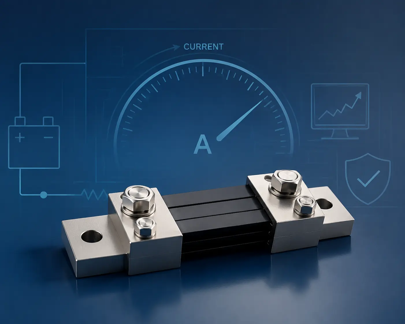
DC current shunt selection should begin with six factors: rated current, millivolt output, accuracy, duty cycle, installation dimensions, and mounting structure. A shunt may match the required current but still be unsuitable if its output does not match the meter, its thermal capacity does not fit the duty cycle, or its terminals cannot be integrated safely.
OEM engineers should evaluate the electrical and mechanical requirements together before approving a standard model or custom DC shunt resistor design.
If you already know your current rating, millivolt output, and mounting requirements, you can review LEEYD standard and custom DC shunt resistor options on our DC shunt product page.
Before selecting a DC shunt, confirm:
- The continuous, peak, and overload current conditions
- The required millivolt output and accuracy
- The available installation space and mounting arrangement
- The duty cycle and operating environment
- The required documentation, inspection records, or compliance information
Start with the Actual Current Profile and Application
A DC current shunt is a calibrated, low-resistance component that produces a measurable millivolt signal as current passes through it. The meter, controller, transducer, or data-acquisition system uses that signal to calculate the actual current.
The rated current alone does not describe the complete operating requirement. Engineers should also consider how the current changes during equipment operation and whether the shunt will work under the actual thermal and mechanical conditions.
Continuous Current
Continuous current is the current that the shunt must carry during normal, sustained operation. This condition affects temperature rise, resistance stability, and long-term performance.
A system that operates near its maximum current for several hours creates a different thermal load from one that reaches the same current for only a few seconds.
For continuous-duty equipment, engineers should confirm:
- Normal operating current
- Maximum sustained current
- Ambient temperature
- Ventilation or cooling conditions
- Expected operating time
- Temperature limits inside the equipment
Do not select a larger current rating automatically without checking measurement resolution. Excessive oversizing may produce a signal that is too small during normal operation.
Peak and Overload Current
Some applications experience short current peaks during startup, switching, charging, welding, or other transient conditions.
The supplier should know:
- Peak current
- Peak duration
- Number of peaks or pulses
- Time between pulses
- Expected overload frequency
Overload capability varies by shunt model, current rating, duration, and installation condition. A short pulse and a sustained overload should not be evaluated in the same way.
Application and Electrical Environment
The application influences both the electrical and mechanical design.
For example:
- Welding equipment may require stable measurement in a high-current and electrically noisy environment.
- Battery and energy-storage systems may operate under long continuous loads.
- DC switchgear may require a structure compatible with busbars and protection cabinets.
- EV-related equipment may need stable current feedback under changing load conditions.
- Test equipment may place greater emphasis on accuracy and long-term stability.
- Compact power equipment may have strict height and mounting-space limits.
The first step in selecting a shunt is therefore not choosing a catalog model. It is defining how the shunt will operate inside the equipment.
Match the Millivolt Output to the Measuring System
A shunt converts current into a low-voltage signal. Its rated millivolt output must match the meter, transducer, controller, or data-acquisition system connected to it.
Common output options available across LEEYD DC shunt series include:
- 40mV
- 50mV
- 60mV
- 75mV
- 100mV
- Custom voltage-drop options for selected projects
These options do not apply to every model. Final availability depends on the current rating, structure, accuracy requirement, and operating conditions.
Confirm the Full-Scale Input
If a meter is designed for a 500A/75mV shunt, it expects 75mV when the current reaches 500A.
Replacing that shunt with a 500A/50mV model changes the relationship between current and signal. The meter would require recalibration or reconfiguration to display the correct current.
The current rating and voltage output must therefore be treated as a matched pair:
500A/75mV is not electrically equivalent to 500A/50mV.OEM engineers should confirm the full-scale input requirement from the meter or control-system datasheet before selecting the shunt.
40mV, 50mV, 75mV, 100mV, or Custom Output
| Output | When It May Fit | What To Confirm |
|---|---|---|
| 40mV / 50mV | Lower voltage drop or legacy meter requirements | Meter input, signal resolution, wiring noise |
| 60mV / 75mV | Common industrial meter and control-system requirements | Full-scale input, heat dissipation, and calibration |
| 100mV or custom | Stronger signal or special system design | Power loss, thermal design, and instrument compatibility |
Consider Signal Strength and Power Dissipation
A higher millivolt output produces a stronger signal, but it also increases power dissipation at the rated current.
Power loss can be estimated as:
Power = Current x Voltage DropFor example, a 1,000A/75mV shunt dissipates approximately:
1,000A x 0.075V = 75WThat heat must be considered in the equipment’s thermal design. A lower millivolt output reduces dissipation but may require greater attention to signal wiring, electrical noise, and measurement resolution.
The best output is not always the highest or lowest value. It is the value that matches the measuring system while remaining acceptable for the thermal and signal environment.
Check the Entire Signal Path
The shunt, signal wires, meter input, controller scaling, and grounding arrangement work as one measurement system.
Before approval, verify:
- Meter or controller full-scale input
- Signal polarity
- Cable length
- Routing near power conductors
- Shielding requirements
- Terminal arrangement
- Calibration method
A correctly rated shunt cannot compensate for an incorrectly configured meter or poor signal wiring. For more technical background, see LEEYD’s guide to DC shunt calculation and working principle.
Select Accuracy According to the System Requirement
Accuracy requirements should come from the equipment’s control, monitoring, protection, or testing function. Selecting the highest available accuracy without examining the application may add cost without improving the complete system.
LEEYD offers model-dependent accuracy options, with higher-precision configurations available for selected series. The required class should be confirmed against the specific shunt model and current range.
Define the Permitted Measurement Error
Engineers should begin with the maximum current error the equipment can tolerate.
Consider:
- Is the reading used only for visual monitoring?
- Does the signal control equipment operation?
- Is it used for protection or alarm functions?
- Will it support laboratory testing or calibration?
- Is long-term data accuracy important?
A display meter for general monitoring may have different requirements from a test bench or closed-loop control system.
The total measurement error also includes the meter, signal conditioner, wiring, analog-to-digital conversion, and calibration method. Specifying a highly accurate shunt does not make the complete measurement chain equally accurate.
Evaluate Temperature and Long-Term Stability
Resistance changes can affect the millivolt output. Manganin is commonly used as a resistive element because it provides stable resistance characteristics across operating temperatures.
However, material selection alone does not determine thermal performance. Engineers should also review:
- Continuous current
- Ambient temperature
- Airflow
- Installation orientation
- Nearby heat sources
- Terminal connection quality
- Duty cycle
- Available cooling space
Rated power capability varies with ambient temperature. Model-specific derating information should be reviewed when the equipment operates under elevated temperatures or long continuous loads.
Confirm How Accuracy Will Be Verified
Before sample approval or batch production, agree on:
- Rated test current
- Required voltage-drop value
- Permitted tolerance
- Test temperature or stabilization conditions
- Measurement equipment
- Sampling or inspection requirements
- Required test records
LEEYD’s production process can include resistance checks, rated voltage-drop verification, output-stability checks, dimensional inspection, and final inspection according to the confirmed product specifications. The exact inspection plan should be agreed upon for the selected model and order.
Check Dimensions, Terminals, and Mounting Before Approval
Mechanical incompatibility is a common reason an electrically suitable shunt cannot be used in an OEM assembly.
Two shunts with the same current rating and millivolt output may have different:
- Overall length, width, and height
- Mounting-hole spacing
- Hole diameter
- Terminal size
- Terminal position
- Base structure
- Sensing-terminal arrangement
- Busbar connection method
OEM engineers should not approve a shunt using electrical parameters alone.
Define the Installation Envelope
Provide the maximum available:
- Length
- Width
- Height
- Mounting footprint
- Clearance around terminals
- Space for cables or busbars
- Space for airflow
A flat-type shunt may suit equipment with limited height. A base-mounted or compact structure may provide better mechanical support in other designs.
The final structure should be selected according to the equipment layout rather than appearance or catalog familiarity.
Confirm Current and Signal Connections
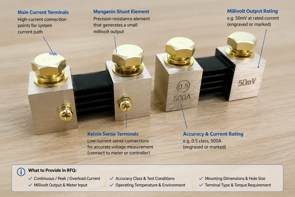
Main current terminals carry the system current. Smaller sensing terminals provide the millivolt signal to the meter or controller.
The connection design should prevent the main terminal contact resistance from affecting the sensing result. Engineers should confirm the current path, sensing points, terminal polarity, and signal-wire routing in the assembly drawing.
Loose, uneven, or contaminated contact surfaces can increase local resistance and temperature. Terminal materials, bolt sizes, contact areas, and assembly requirements should therefore be included in the technical review.
Avoid Mechanical Stress
A shunt should not be forced into an assembly when mounting holes or busbars do not align correctly. Bending, twisting, or loading the resistive element may affect calibration or damage the joined structure.
The assembly should account for:
- Hole-position tolerance
- Busbar alignment
- Thermal expansion
- Vibration
- Installation torque
- Mechanical support
- Service access
A drawing review or physical installation check should be completed before approving mass production.
Choose a Standard Series or a Custom Configuration
A standard shunt can shorten development time when its electrical rating and mechanical structure already match the equipment. A custom configuration is more appropriate when the installation or performance requirements cannot be met by an existing model.
The standard and custom DC shunt resistor range from LEEYD includes standard, flat-type, welding, precision, high-current, compact, regional, energy-system, and customized structures.
| Shunt Series or Type | Typical Selection Reason | Important Confirmation |
|---|---|---|
| FL-2 standard shunts | General industrial current measurement | Current, output, accuracy, and mounting dimensions |
| FL-2F flat-type shunts | Limited installation height | Footprint, cooling, and terminal access |
| FL-19 welding shunts | Welding and high-frequency power environments | Current profile, interference, duty cycle, and mounting |
| FL-27 precision shunts | Testing, calibration, and precision measurement | Accuracy, stability, test conditions, and documentation |
| FL-29 / FL-39 high-current shunts | High-current industrial equipment | Thermal conditions, busbars, peak current, and structure |
| TD-15 compact shunts | Equipment with limited installation space | Mechanical support, heat dissipation, and terminal layout |
| Energy-system shunts | Battery and energy-storage equipment | Continuous current, operating conditions, and system integration |
| Customized shunts | Non-standard electrical or mechanical requirements | Drawing, specifications, validation, and production controls |
This table provides a starting point, not a final model recommendation. Available specifications vary by series and current rating.
When a Custom Shunt May Be Necessary
Customization may be appropriate when the project requires:
- A non-standard current rating
- A specific voltage drop
- Different overall dimensions
- Modified terminal sizes or positions
- Custom mounting holes
- Limited installation height
- Different markings or labels
- Application-specific materials
- Special packaging or documentation
A custom project should move through specification review, drawing confirmation, prototype validation, and controlled production transfer.
For non-standard current ratings, voltage drops, mounting holes, terminal materials, or busbar layouts, LEEYD can review drawings or samples before confirming a custom DC shunt resistor design.
Validate the Prototype in the Actual Assembly
A prototype should be reviewed for more than electrical output.
OEM engineers should verify:
- Dimensional fit
- Mounting-hole alignment
- Terminal access
- Busbar or cable connection
- Signal polarity
- Voltage-drop output
- Temperature behavior
- Clearance and airflow
- Markings
- Installation procedure
Sample approval should record the final drawing, electrical specifications, materials, inspection requirements, markings, and packaging. These confirmed requirements can then be transferred into batch production.
Use a Complete DC Current Shunt Selection Checklist
The following information allows a manufacturer to evaluate a standard model or custom design more accurately.
| Selection Item | Information To Provide | Why It Matters |
|---|---|---|
| Application | Equipment type and shunt function | Defines the operating and integration requirements |
| Rated current | Normal and maximum continuous current | Determines the basic current capacity |
| Peak current | Value, duration, and frequency | Supports overload and structural evaluation |
| Voltage drop | 40mV, 50mV, 60mV, 75mV, 100mV, or another requirement | Must match the measuring system |
| Accuracy | Required class or permitted error | Affects model and testing requirements |
| Duty cycle | Continuous, intermittent, or pulsed operation | Affects thermal evaluation |
| Environment | Ambient temperature, airflow, vibration, and nearby heat sources | Influences performance and mounting |
| Dimensions | Maximum size and installation envelope | Confirms mechanical compatibility |
| Terminals | Material, size, location, and connection method | Affects current flow and assembly |
| Mounting | Hole positions, base type, and orientation | Prevents installation conflicts |
| Quantity | Prototype and production quantities | Supports process and schedule planning |
| Documentation | Drawings, inspection records, or compliance documents | Defines order and approval requirements |
Providing a drawing, datasheet, product photo, or reference sample can reduce uncertainty during selection.
Frequently Asked Questions
Can I select a DC shunt using only the rated current?
No. Rated current is only one selection factor. You must also confirm millivolt output, accuracy, continuous and peak current conditions, duty cycle, temperature, dimensions, terminals, and mounting. A shunt may carry the required current but still produce the wrong signal or fail to fit the equipment. Send the complete electrical and mechanical requirements before approving a model.
Can a 75mV shunt replace a 50mV shunt with the same current rating?
Not without checking the measuring system. A 75mV and 50mV shunt produce different full-scale signals at the same current. The meter, controller, or signal conditioner must match the selected output or be recalibrated. The higher voltage drop also changes power dissipation. Treat the current rating and millivolt output as one combined specification.
How do I choose between a standard and custom DC current shunt?
Choose a standard DC current shunt when the current rating, millivolt output, accuracy, dimensions, and mounting structure already match your equipment. Choose a custom DC shunt resistor when the project requires a non-standard current rating, special voltage drop, modified terminals, different mounting holes, limited installation space, or a specific busbar layout.
Should I choose a shunt with a much higher current rating for safety?
Not automatically. A higher rating may provide additional thermal capacity, but excessive oversizing can reduce the signal level within the equipment’s normal operating range. The correct margin depends on continuous current, peak current, pulse duration, ambient temperature, cooling, and required measurement resolution. Ask the manufacturer to evaluate the actual load profile rather than applying one universal percentage.
What information is needed for a custom DC shunt?
Provide rated current, millivolt output, accuracy, operating conditions, dimensions, mounting method, terminal requirements, quantity, and application. A drawing or reference sample is especially helpful. The manufacturer should review feasibility before confirming the structure. Prototype validation should cover dimensional fit, electrical output, installation, and application conditions before batch production.
What should OEM engineers verify before approving a sample?
Verify the electrical output, accuracy requirement, dimensions, mounting holes, terminals, polarity, installation fit, markings, and required documentation. The sample should also be evaluated under representative operating conditions when possible. Approval records should identify the final drawing and agreed inspection requirements so that production units can be checked against the same reference.
Review Your Shunt Requirements Before Model Approval
A reliable DC current shunt selection starts with a complete specification, not a model number alone. Prepare the application, rated and peak current, voltage drop, accuracy, duty cycle, dimensions, terminal layout, mounting requirements, and expected quantity.
If an existing series does not fit your equipment, send your drawing, datasheet, or reference sample to LEEYD. Our team can review the requirements and recommend a standard model or custom DC shunt resistor configuration before prototype approval.
Button:
Send Your DC Shunt RequirementsTell Us What You Need
Need help with product selection, customization, or a quotation? Send us your specifications, drawings, quantity, and application requirements.
Our team will review the information and contact you to confirm the next step.