
A 10kV lightning arrester should be selected from the actual power system conditions, not from the “10kV” label alone. For distribution transformers, switchgear, cable terminations, overhead lines, and industrial power systems, buyers need to confirm the system voltage, grounding method, maximum continuous operating voltage, discharge current, protection level, housing, installation environment, and monitoring requirements before choosing a zinc oxide arrester model.
This guide explains how to choose a 10kV zinc oxide lightning arrester and what information engineering or purchasing teams should prepare before requesting a quotation. For the full product range, visit the LEEYD zinc oxide lightning arrester page.
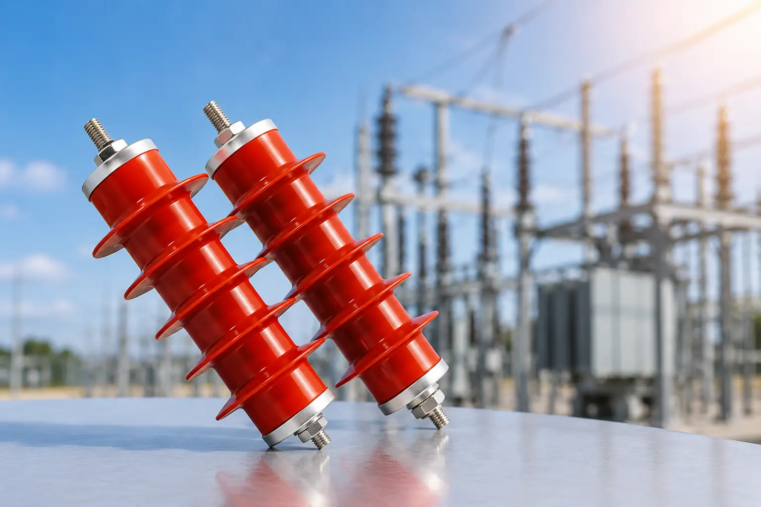
Quick Selection Table for a 10kV Lightning Arrester
Before comparing models, use this quick table to collect the basic project information. It helps the supplier check whether the selected arrester is suitable for the electrical system and the installation site.
| Selection Item | Information to Confirm | Why It Matters |
|---|---|---|
| System voltage | Nominal voltage, phase-to-phase or phase-to-earth voltage, frequency | Prevents confusion between system voltage and arrester rated voltage |
| Grounding method | Effectively grounded, resistance grounded, isolated neutral, or other arrangement | Affects temporary overvoltage conditions during earth faults |
| Arrester rating | Rated voltage, MCOV, discharge current, residual voltage, reference voltage | Confirms continuous operation and protective performance |
| Protected equipment | Transformer, switchgear, cable line, capacitor bank, motor, or distribution line | Different equipment may require different protection coordination |
| Installation environment | Indoor/outdoor, altitude, pollution level, moisture, temperature, space | Influences housing, creepage distance, mounting, and long-term reliability |
| Accessories | Bracket, disconnector, terminal hardware, insulating base, monitor, surge counter | Ensures the arrester can be installed and maintained correctly |
A 10kV System Does Not Always Use a 10kV Arrester Rating
One common mistake is assuming that a 10kV system must use an arrester with a 10kV rated voltage. In practice, the arrester rating is selected according to the network voltage, grounding method, temporary overvoltage behavior, insulation coordination, and applicable project standard.
For example, some LEEYD 10kV zinc oxide surge arrester models are listed with a rated voltage of 17kV and an MCOV of 13.6kV. These values are not the same as the nominal system voltage. They describe different electrical characteristics and must be reviewed together.
If the project document only says “10kV lightning arrester,” ask for the complete electrical specification before confirming a model. A higher arrester voltage is not automatically better, because it may increase the protective level and reduce the protection margin for the equipment.
Key Electrical Parameters to Check
A zinc oxide arrester contains metal oxide varistor elements that remain highly resistive under normal operating voltage and conduct surge current when overvoltage occurs. To select the correct model, each electrical rating must be understood separately.
For general technical background on this type of protective device, see this external reference on surge arresters. For LEEYD product selection, use the model data and project-specific checks below.
Rated Voltage
Rated voltage is a designated arrester rating used to identify the arrester class and operating characteristics. It is not simply the same as the 10kV system voltage. Buyers should compare the rated voltage with the system grounding method and temporary overvoltage conditions.
Maximum Continuous Operating Voltage
Maximum continuous operating voltage, often called MCOV, is the power-frequency voltage that can be continuously applied to the arrester under specified conditions. If MCOV is too low for the actual system condition, the arrester may experience unnecessary stress. If the selected rating is too high, the protection level may not be optimized for the equipment.
Nominal Discharge Current
Nominal discharge current describes the specified surge-current condition used for arrester testing and classification. The required value depends on the protected equipment, system exposure, installation location, and project standard. Do not compare discharge-current numbers without checking the test waveform and class.
Residual Voltage
Residual voltage is the voltage across the arrester while it is conducting a specified surge current. It is important for insulation coordination because it indicates the protective level seen by the protected equipment. Residual voltage should be compared under the same discharge-current condition.
DC 1mA Reference Voltage
DC 1mA reference voltage is used as a product characteristic for verification and comparison. It should not be treated as the normal operating voltage of the system. If a project requires this value, confirm it against the exact model datasheet.
| Parameter | What It Means | Buyer Check |
|---|---|---|
| Nominal system voltage | The voltage class of the power network | Confirm phase-to-phase or phase-to-earth reference |
| Rated voltage | The designated arrester rating | Match with grounding and temporary overvoltage conditions |
| MCOV | Continuous voltage withstand capability | Compare with actual continuous operating voltage |
| Discharge current | Surge-current test condition | Check waveform, class, and project requirement |
| Residual voltage | Protective level during surge conduction | Compare with insulation coordination requirements |
| Reference voltage | Verification characteristic at specified DC current | Check exact datasheet value for the selected model |
Where Are 10kV Zinc Oxide Arresters Used?
10kV zinc oxide lightning arresters are commonly used in medium-voltage distribution and industrial power protection. The same nominal voltage may appear in different equipment, so the application should be stated clearly in the inquiry.
- Distribution transformers and transformer terminals.
- Medium-voltage switchgear and cable compartments.
- Overhead distribution lines and cable transition points.
- Industrial power systems and factory distribution networks.
- Capacitor banks, motors, and other protected equipment where surge protection is required.
If the application is gas-insulated switchgear instead of an outdoor or cabinet-mounted arrester, review the separate GIS surge arresters product page.
Check Housing, Mounting, and Installation Environment
Electrical data alone cannot confirm that a 10kV surge arrester will fit the project. The housing, creepage distance, terminals, mounting base, cable direction, and available space must also match the installation condition.
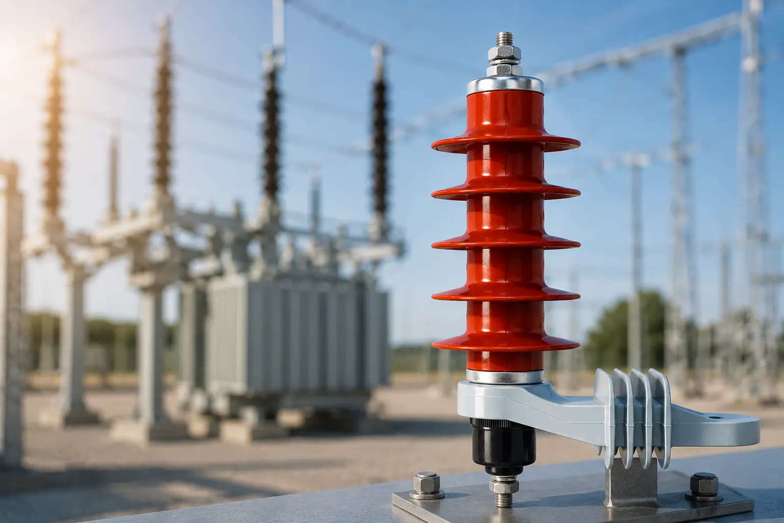
For outdoor applications, provide the expected ambient temperature, altitude, pollution condition, moisture exposure, and required housing structure. For switchgear or compact installations, confirm compartment space, phase spacing, clearance, cable direction, mounting hole layout, and maintenance access.
If the project requires a surge counter, leakage current indication, or remote monitoring, connect the arrester specification with the LEEYD arrester monitoring solutions page during selection. Monitoring accessories should be planned before finalizing the installation layout.
10kV Lightning Arrester vs Zinc Oxide Surge Arrester
Buyers often use “lightning arrester” and “surge arrester” in the same inquiry. In many medium-voltage projects, both terms refer to equipment used to limit transient overvoltage and protect power equipment. “Zinc oxide” or “metal oxide” describes the arrester material and operating principle.
For broader technical background, see the LEEYD guide to zinc oxide surge arresters. That page explains ZnO/MOV arrester principles and general selection factors, while this page focuses on 10kV system selection.
What Buyers Should Send for Model Recommendation
To recommend a suitable 10kV zinc oxide lightning arrester, LEEYD should receive both electrical and mechanical project details. A complete inquiry reduces back-and-forth and helps avoid selecting a model only by nominal voltage.
| RFQ Item | What to Provide |
|---|---|
| System information | Nominal voltage, frequency, phase reference, grounding method |
| Electrical requirements | Rated voltage, MCOV, discharge current, residual voltage, reference voltage if specified |
| Protected equipment | Transformer, switchgear, cable line, overhead line, capacitor bank, motor, or other equipment |
| Installation | Indoor/outdoor, mounting method, terminal direction, available space, environmental conditions |
| Standards and project documents | Technical specification, drawing, datasheet requirement, test or certification requirement |
| Accessories | Disconnector, bracket, insulating base, surge counter, leakage current monitor, remote monitoring need |
| Commercial details | Quantity, destination market, project schedule, replacement or new installation |
If you are comparing suppliers for a larger project, you can also review LEEYD’s lightning and surge arrester capabilities before sending the technical specification.
Recommended Selection Workflow
- Confirm the actual 10kV system voltage and whether the value is phase-to-phase or phase-to-earth.
- Confirm the grounding method and expected temporary overvoltage conditions.
- Compare rated voltage and MCOV with the system requirements.
- Check discharge current and residual voltage against the project specification.
- Match housing, terminals, mounting method, and installation space.
- Confirm whether monitoring accessories such as a surge counter or leakage current monitor are required.
- Send the complete specification, drawing, quantity, and destination market for model confirmation.
Frequently Asked Questions
What is a 10kV lightning arrester used for?
A 10kV lightning arrester is used to protect medium-voltage distribution equipment from transient overvoltage. Typical applications include distribution transformers, switchgear, overhead lines, cable terminations, and industrial power systems.
Is a 10kV lightning arrester the same as a 10kV surge arrester?
In many buyer inquiries, the two phrases are used for the same type of protective device. A supplier should still confirm the exact system voltage, arrester rating, MCOV, discharge current, and installation requirements before recommending a model.
Why do some 10kV systems use a 17kV arrester rating?
The nominal system voltage and arrester rated voltage describe different things. The correct arrester rating depends on grounding method, continuous operating voltage, temporary overvoltage, and protection coordination. Buyers should follow the project specification or request a technical review.
What information is needed to quote a zinc oxide lightning arrester?
Provide the voltage level, grounding method, arrester rating if specified, MCOV, discharge current, protected equipment, installation environment, mounting method, accessories, quantity, and any project drawing or datasheet requirement.
Should a surge counter be selected together with the arrester?
If the project needs operation counting, leakage current indication, inspection records, or remote condition monitoring, the surge counter or arrester monitor should be considered during the arrester selection stage. This avoids mechanical and wiring conflicts later.
Request 10kV Arrester Model Support
LEEYD supplies zinc oxide lightning arresters and related monitoring solutions for distribution, substation, switchgear, transformer protection, and industrial power applications. For a 10kV lightning arrester recommendation, send your voltage level, grounding method, technical specification, installation environment, accessories, and quantity through the LEEYD technical inquiry page.