
A Hall current sensor output signal must match the device that receives the measurement. In industrial systems, that receiving device may be a PLC, display meter, protection relay, controller, data acquisition module, or alarm circuit. If the output signal is wrong, the sensor may measure current correctly but still fail to work with the control system.
This guide explains common Hall current sensor output signals, including voltage output, current output, transmitter output, and switch output. It also shows what buyers should confirm before selecting a model. For available product families, see LEEYD Hall Sensors.
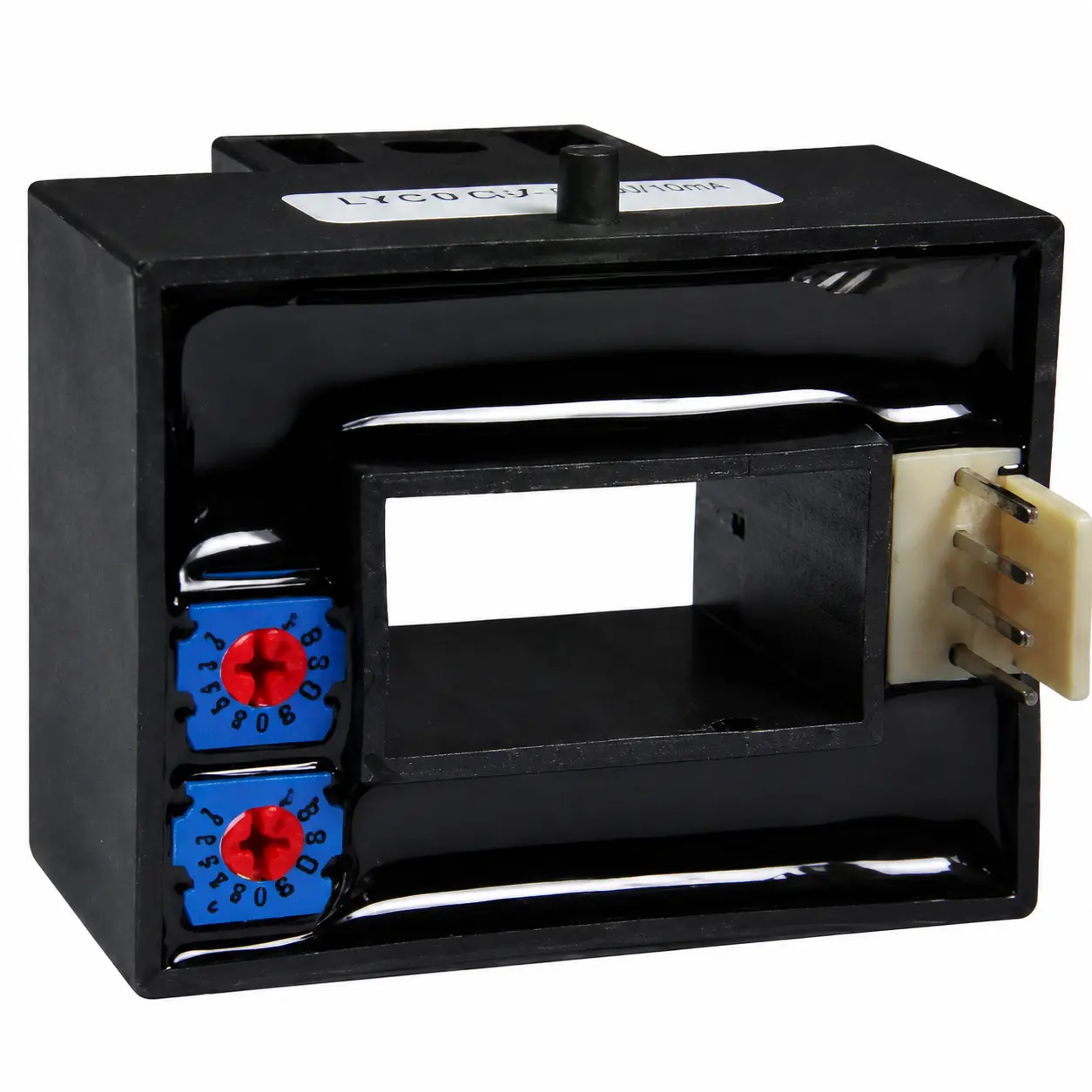
Why the Output Signal Matters
The output signal is the interface between the current sensor and the rest of the electrical system. A sensor may be installed around the correct conductor and rated for the correct current, but the project can still have problems if the output does not match the meter, PLC, or controller input.
Before choosing a Hall current sensor, confirm whether the system needs an analog measurement signal, a standard transmitter signal, or a switch signal for threshold detection. This decision affects wiring, calibration, monitoring accuracy, and control logic.
Voltage Output Hall Current Sensors
A voltage output Hall current sensor provides a voltage signal proportional to the measured current. This output may be used by a controller, display instrument, analog input module, or signal acquisition circuit. The exact output range depends on the sensor design and power supply.
Voltage output is often useful when the sensor is close to the control circuit and the receiving device has a compatible analog voltage input. Buyers should confirm the output range, zero-current reference, direction, supply voltage, and whether the measured current is DC, AC, pulse, or bidirectional.
Current Output and Transmitter Signals
Current output or transmitter output is commonly used in industrial control cabinets and monitoring systems. A transmitter converts the measured current into a signal that is easier for a PLC or monitoring device to read. This can be useful when the signal must travel through cabinet wiring or when the system requires a standard industrial signal.
When selecting a Hall current transmitter, confirm the input current range, output signal type, power supply, load resistance, wiring method, and response requirement. For DC and AC measurement differences, read Hall Effect Current Sensor for DC and AC Current Measurement.
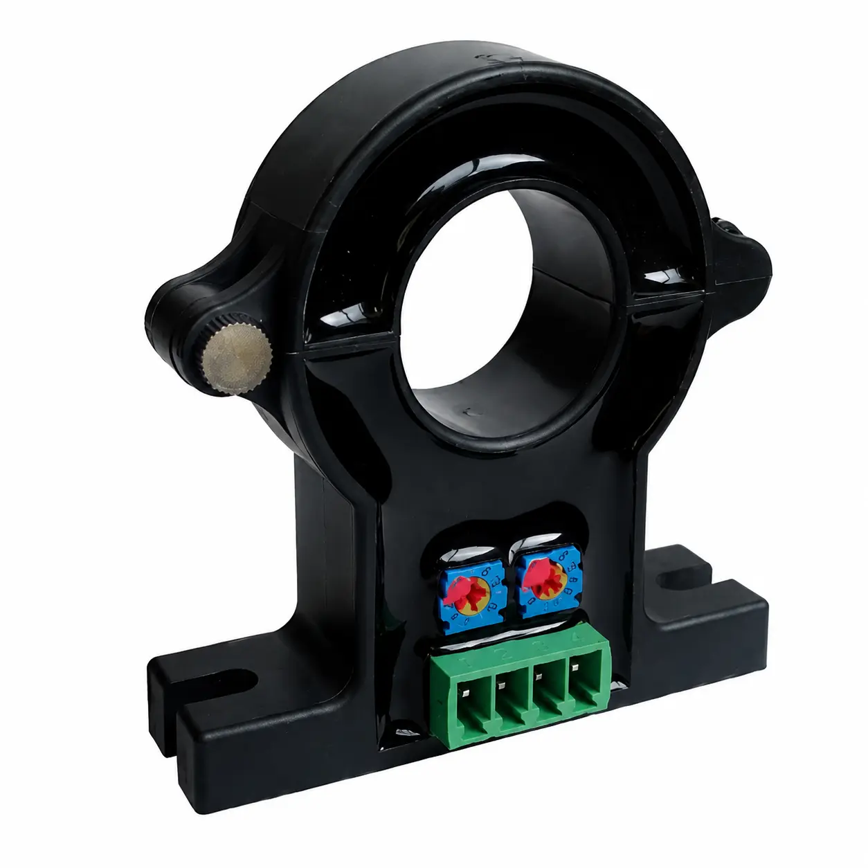
Switch Output for Current Detection
A switch output Hall current sensor is used when the system needs to detect whether current is present, above a set threshold, or outside a required range. Instead of providing a continuous analog measurement value, the sensor provides a switching signal for alarm, protection, interlock, or status detection.
Switch output is useful for load detection, overcurrent alarms, motor status monitoring, heater status detection, and protection circuits. Buyers should confirm the threshold value, reset condition, output logic, response time, and whether the threshold must be adjustable.
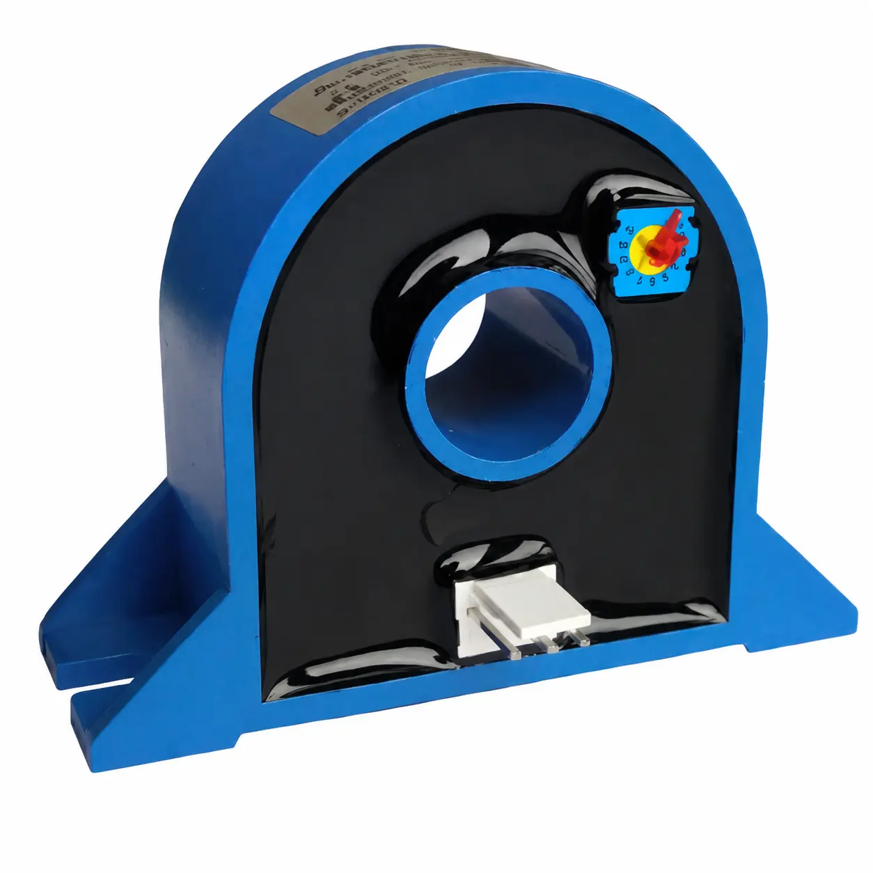
Common Hall Sensor Output Options
The table below summarizes the common output choices and where they are typically used.
| Output Signal | Typical Use | What to Confirm |
|---|---|---|
| Voltage output | Controller, display meter, analog acquisition circuit | Output range, zero reference, supply voltage, input compatibility |
| Current output | Industrial monitoring and control systems | Signal range, load resistance, wiring distance, power supply |
| Transmitter output | PLC, cabinet monitoring, remote signal collection | Input current, output signal, response time, wiring method |
| Switch output | Alarm, protection, load detection, current status | Threshold, reset logic, output type, response condition |
| Custom signal | OEM equipment or special control systems | Input/output relationship, supply, accuracy, connector, wiring |
How to Match Output Signal to the Receiving Device
The safest way to select the output is to start from the receiving device. Check the input terminals and signal range of the PLC, meter, controller, or relay before choosing the current sensor. This avoids selecting a sensor that measures correctly but cannot be read by the system.
| Receiving Device | Common Requirement | Selection Note |
|---|---|---|
| PLC analog input | Standard voltage or current signal | Confirm input range and wiring type |
| Display meter | Compatible analog signal or transmitter output | Confirm scale and signal mapping |
| Controller | Voltage or current feedback signal | Confirm response time and signal reference |
| Protection circuit | Switch output or alarm signal | Confirm threshold and reset behavior |
| Data acquisition system | Stable analog output | Confirm sampling rate, noise, and accuracy |
Output Signal and Sensor Type
The output signal also relates to the sensor structure. Open loop Hall current sensors are often used for general isolated current measurement. Closed loop Hall current sensors are selected when accuracy, response speed, and linearity are more important. Current transmitters and current switches are selected when the output function is already defined by the control system.
If you are still deciding between open loop and closed loop structures, see Open Loop vs Closed Loop Hall Effect Current Sensors. If you need a full selection checklist, see How to Select a Hall Current Sensor.
Information to Provide Before Ordering
To recommend the correct Hall current sensor output signal, the supplier needs both electrical and control-system information. Provide the measured current range and also the signal expected by the receiving device.
| Item | Information to Provide |
|---|---|
| Measured current | DC, AC, pulse, rated current, peak current, and direction |
| Receiving device | PLC, meter, controller, relay, alarm circuit, or data module |
| Required output | Voltage, current, transmitter signal, switch output, or custom signal |
| Power supply | Available supply voltage and single or dual supply requirement |
| Accuracy and response | Measurement accuracy, response speed, and drift requirement |
| Mechanical details | Aperture size, conductor type, mounting method, and wiring space |
How LEEYD Supports Hall Sensor Output Selection
LEEYD can help select Hall current sensors, Hall current transmitters, and current switch sensors according to measured current, output signal, receiving device, power supply, aperture size, and application conditions. The goal is to match both the current measurement requirement and the control-system interface.
For model recommendation, provide the current type, rated current, peak current, required output signal, receiving device, supply voltage, conductor size, and mounting space. You can contact LEEYD for Hall current sensor output selection with your project details.
FAQ
What output signal does a Hall current sensor provide?
A Hall current sensor may provide voltage output, current output, transmitter output, switch output, or a custom signal depending on the model and application.
How do I choose between voltage output and current output?
Choose according to the receiving device. If the PLC, meter, or controller requires voltage input, use a compatible voltage output. If the system needs an industrial signal over cabinet wiring, current output or transmitter output may be more suitable.
When should I use a current switch sensor?
Use a current switch sensor when the system needs threshold detection, alarm output, load status monitoring, or protection logic instead of continuous analog current measurement.
Can the output signal be customized?
In many projects, output signal requirements can be reviewed based on the current range, receiving device, power supply, and control logic. Provide the required signal range before ordering.
What information should I send for output selection?
Please send the measured current type, rated current, peak current, required output signal, receiving device, power supply, aperture size, and installation method.